XTA DC1048 User Manual
Page 29
Operator’s Manual
DC1048 Integrated Audio Management
Page 29
2
3
1
4
5
6
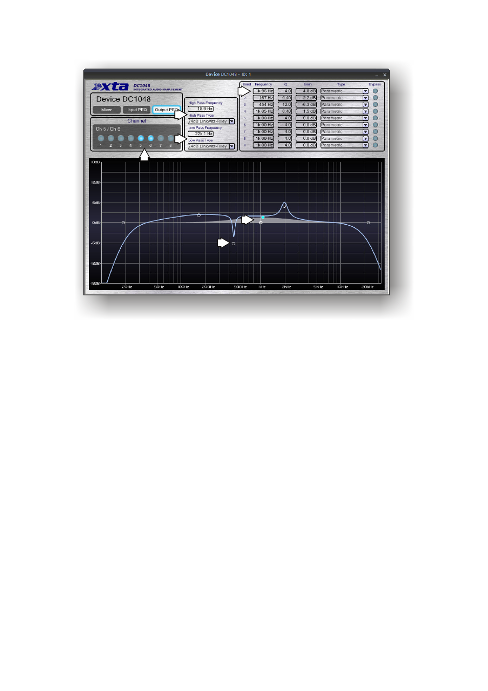
1: Output channel select: swap between the channel(s) to adjust. Linked
channels will have their buttons illuminated together.
2: Crossover filters: high pass filter: enter frequency numerically by double
clicking on the readout, or single click on the readout and move vertically to
adjust. Response curve will show updates in real time. Note that the node for
the filter will highlight on the curve, and this can also be dragged to adjust the
frequency. Filter type is selected via the drop-down list.
3: Crossover filters: low pass filter: enter frequency numerically by double
clicking on the readout, or single click on the readout and move vertically to
adjust. Response curve will show updates in real time. Note that the node for
the filter will highlight on the curve, and this can also be dragged to adjust the
frequency. Filter type is selected via the drop-down list.
4: Parametric filters: frequency, ‘Q’ and filter gain can all be entered using
methods explained above for the high/low pass filters. Additionally, each band
may be individually bypassed, and the filter type chosen from the drop down list.
More information on some of these individual filters and their usage is given in
the appendix on page 50.
5: Response curve : filter node: adjusting a filter will illuminate its node on the
curve and this allows it to be dragged in real time, updating the tabular
information and adjusting the unit. For parametric filters, holding down the left
mouse button whilst moving the scroll wheel will change the ‘Q’ of the filter.
6: Response curve: shadow EQ: the grey response shown in addition to the
blue overall curve, will change depending on the filter currently being adjusted,
and shows just its contribution to the overall response.