1 backplane connectors, 1 zone1 (p10) power connector, 2 zone2 data transport zd connector – Artesyn ATCA-7350 Installation and Use (September 2014) User Manual
Page 64: Controls, leds and connectors
Controls, LEDs and Connectors
ATCA-7350 Installation and Use (6806800G59G)
64
3.4.1
Backplane Connectors
3.4.1.1
Zone1 (P10) Power connector
The definition of the Zone 1 (P10) connector complies with PIGMIG 3.0.
3.4.1.2
Zone2 Data Transport ZD connector
The definition of the Zone 2 connector is a subset of that defined in PIGMIG3.0. The ATCA-7350
supports the update channel interface on P20, as well as the Base interface and Fabric interface
on P23 only.
The ATCA-7350 supports one Update channel connecting to the redundant slot. This channel
is on the P20 connector, which is Port 0 defined in PICMIG3.0. PICMIG3.0 defines five Update
ports in total. The other four ports are reserved. Reserved ports are terminated.
Face Plate
Connectors
J19/J40
Drive Bay 1/0
29-Pin, SAS Connector
J14
USB
8-Pin, Dual USB port connector
J22
COM
8-Pin, RJ45 Serial port connector
J44
SAS
Connector
16-Pin, InfiniBand receptacle
On-Board
Memory
Module
Connectors
J25/J39/J2
7/J28
FBD
Connectors
240-Pin, Fully buffered DIMM slots
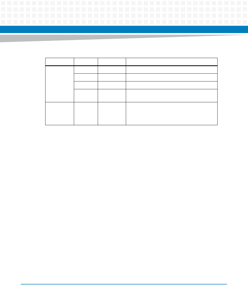
Table 3-2 Positions and Description of the Connectors of the ATCA-7350 (continued)
Location
REFDES
Description
Details