Controls, leds and connectors – Artesyn ATCA-7350 Installation and Use (September 2014) User Manual
Page 72
Controls, LEDs and Connectors
ATCA-7350 Installation and Use (6806800G59G)
72
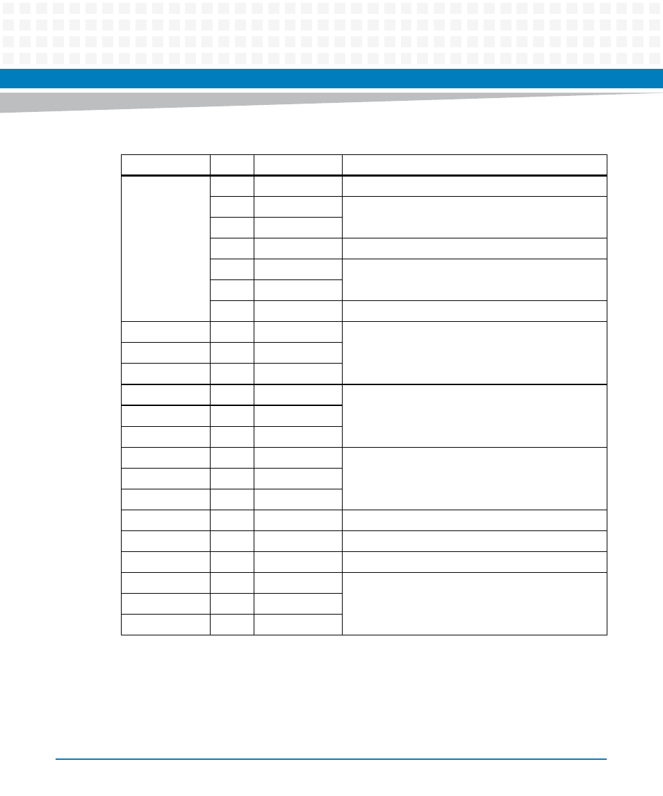
Secondary
Signals
S8
GROUND
Connected to the logic Ground of ATCA-7350
S9
TS+
Secondary Transmitting Pair. Not connected on ATCA-
7350.
S10
TS-
S11
GROUND
Connected to the logic Ground of ATCA-7350
S12
RS-
Secondary Receiving Pair. Not connected on ATCA-
7350.
S13
RS+
S14
GROUND
Connected to the logic Ground of ATCA-7350
P1
V33
3.3V Power Supply. Connected to ATCA-7350 3.3V
power plane.
P2
V33
P3
V33, precharge
P4
GROUND
Connected to the logic Ground of ATCA-7350
P5
GROUND
P6
GROUND
P7
V5, precharge
5V Power Supply. Connected to ATCA-7350's 5V
power plane through the slow start control circuit.
P8
V5
P9
V5
P10
GROUND
Connected to the logic Ground of ATCA-7350
P11
READY LED
Not used on ATCA-7350, No connection.
P12
GROUND
Connected to the logic Ground of ATCA-7350
P13
V12, precharge
12V Power Supply. Connected to ATCA-7350's 12V
power plane through the slow start control circuit.
P14
V12
P15
V12
Table 3-8 SAS Connector Pin Assignments (continued)
Segment
PIN
Name
Description