Flowserve 500+ Series Logix User Manual
Page 14
User Instructions - Logix® 500+ Series Digital Positioners FCD LGENIM0105-10 11/13
flowserve.com
14
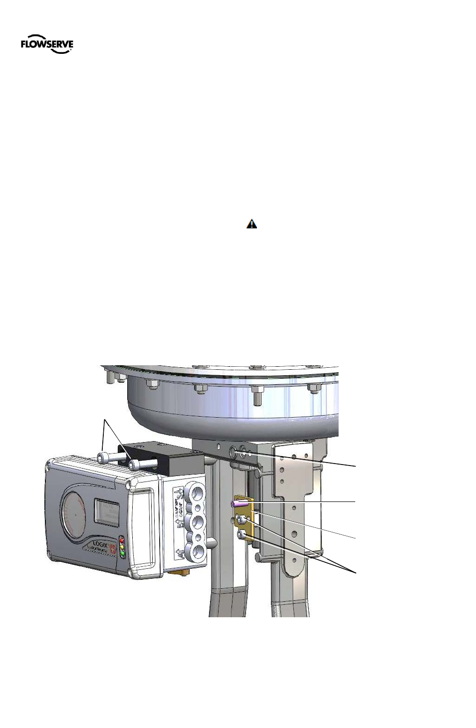
Refer to Figure 6: FlowTop Mounting.
4
Assemble the take-off pin to the take-off plate and
mount the take-off plate to the valve stem using the two
screws. Adjust the follower pin to match the correct
location as indicated on the follower arm’s embossed
scale.
5
Place the actuator O-ring.
6
Place the positioner on the actuator, ensuring the take-
off pin is inside the follower arm slot. Adjust the
follower arm as needed.
NOTE: The feedback shaft has a clutch mechanism that
allows for over-rotation of the shaft for easy adjustments.
7
Use the actuator screws to secure the positioner in
place.
8
Connect regulated air supply to appropriate port in
manifold. See section 6 TUBING.
9
Connect the power to the 4-20 mA terminals. See
section 7 ELECTRICAL CONNECTIONS.
10
Remove main cover and locate DIP switches and
QUICK-CAL/ACCEPT button.
11
Refer to sticker on main board cover and set DIP
switches accordingly. See section 8 STARTUP.
12
Press the QUICK-CAL/ACCEPT button for three to four
seconds or until the positioner begins to move. The
positioner will now perform a stroke calibration.
13
If the calibration was successful the green LED will blink
GGGG or GGGY and the valve will be in control mode.
14
If calibration fails, as indicated by a RGGY blink code,
retry the calibration. If it still fails, the feedback values
were exceeded and the arm must be adjusted away
from the positioner’s limits. Rotate the feedback shaft
so that the full free travel of the feedback shaft is in the
range of the actuator movement. Optionally, continue
to attempt the calibration. Each calibration attempt
adjusts the acceptable limits and it should pass
eventually.
CAUTION: Remember to remove the air supply before
re-adjusting take-off arm.
NOTE: If mounted properly, the follower arm should be
horizontal when the valve is at 50% stroke and should move
approximately ±30° from horizontal over the full stroke of the
valve.
NOTE: To virtually eliminate non-linearity, use the
Linearization feature on the Custom Characterization page of
the DTM.
Actuator Screws
Take-Off Plate
Take-Off Pin
Take-Off Plate Screws
Actuator O-ring
Figure 6: FlowTop Mounting