2 specifications, 1 input signal, 2 air supply – Flowserve 500+ Series Logix User Manual
Page 8: 3 pneumatic output, 4 stroke output, 5 analog output – multi-function card, 6 remote mount specifications, Specifications, Nput, Ignal
User Instructions - Logix® 500+ Series Digital Positioners FCD LGENIM0105-10 11/13
flowserve.com
8
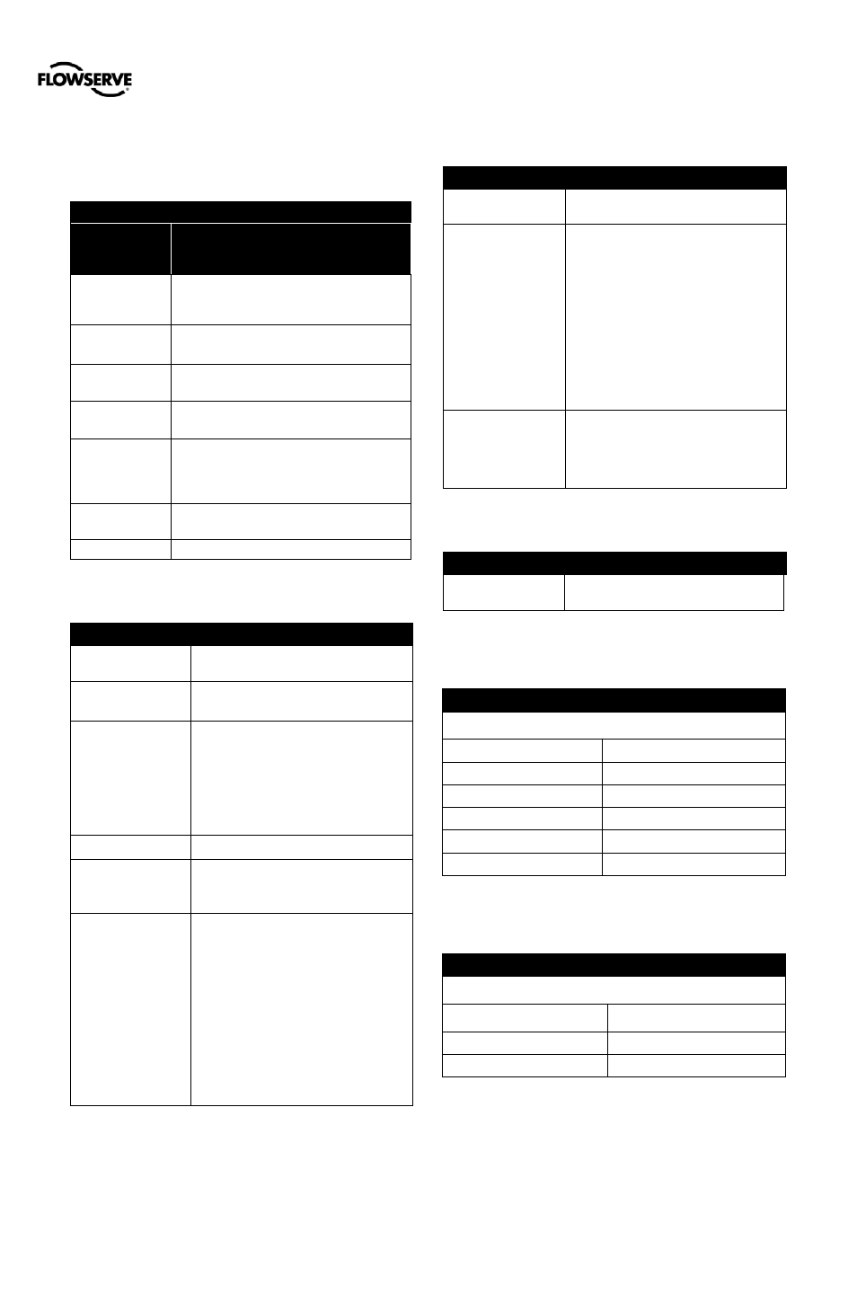
2 SPECIFICATIONS
2.1
Input Signal
Table 1: Input Signal
Positioner Alone
or with
Multi-Function Card
Power Supply
Two-wire, 4-20 mA
10.0 VDC plus line losses.
Input Signal
Range
4 - 20 mA (HART)
Compliance
Voltage
10.0 VDC
@ 20 mA
Effective
Resistance
500 Ω @ 20 mA Typical
Minimum
Required
Operating Current
3.8 mA
Maximum Shut-
down Current
3.6 mA
Communications
HART protocol
2.2
Air Supply
Table 2: Air Supply
Minimum Input
Pressure
1.5 Bar (22 PSI)
Maximum Input
Pressure
Single Acting Relay – 6.2 Bar (90 PSI)
Double Acting Relay – 10.3 Bar (150 PSI)
Air Supply Quality
The air supply must be free from moisture,
oil and dust by conforming to the ISA
7.0.01 standard. (A dew point at least 18
degrees Fahrenheit below ambient
temperature, particle size below five
microns—one micron recommended—and
oil content not to exceed one part per
million).
Operating Humidity
0 - 100% non-condensing
Acceptable Supply
Gasses
Air, sweet natural gas, nitrogen and CO2
are acceptable supply gasses.
Sour natural gas is not acceptable.
Air Consumption
Single Acting Relay –
0.069 Nm³/h @ 1.5 bar
(0.041 SCFM @ 22 PSI)
0.082 Nm³/h @ 4.1 bar
(0.050 SCFM @ 60 PSI)
Double Acting Relay –
0.297 Nm³/h @ 1.5 bar
(0.175 SCFM @ 22 PSI)
0.637 Nm³/h @ 4.1 bar
(0.375 SCFM @ 60 PSI)
2.3
Pneumatic Output
Table 3: Pneumatic Output
Output Pressure
Range
0 to 100% of air supply pressure.
Output Air Capacity
Single Acting Relay –
9.06 Nm³/h @ 1.5 bar
(5.33 SCFM @ 22 PSI)
20.8 Nm³/h @ 4.1 bar
(12.2 SCFM @ 60 PSI)
Double Acting Relay –
14.3 Nm³/h @ 1.5 bar
(8.44 SCFM @ 22 PSI)
30.6 Nm³/h @ 4.1 bar
(18.0 SCFM @ 60 PSI)
Primary Output Ports
(Port is pressurized in
energized state. Port
is exhausted upon loss
of power.)
Single Acting Relay – Port B
Double Acting Relay – Port A
2.4
Stroke Output
Table 4: Stroke Output
Feedback shaft
Rotation
Min 15°, Max 90°
45° recommended for linear applications.
2.5
Analog Output – Multi-Function Card
Table 5: 4 to 20 mA Analog Output Specification
For entity parameters, see section 3 HAZARDOUS AREA
CERTIFICATIONS.
Power Supply Range
10.0 to 40 VDC, (24 VDC Typical)
Current Signal Output
4 to 20 mA
Linearity
1.0% F.S.
Repeatability
0.25% F.S.
Hysteresis
1.0% F.S.
Operating Temperature
-52 to 85°C (-61.6 to 185°F)
2.6
Remote Mount Specifications
Table 6: Remote Mount Specifications
For entity parameters, see section 3 HAZARDOUS AREA
CERTIFICATIONS.
Remote Mount Device
Use only with Logix® Remote
Mount Option device.
Max Cable and Tube Distance 30.5 m (100 ft)
Operating Temperature
-52 to 85°C (-61.6 to 121°F)