5 adjusting the display contrast – Flowserve 500+ Series Logix User Manual
Page 32
User Instructions - Logix® 500+ Series Digital Positioners FCD LGENIM0105-10 11/13
flowserve.com
32
typically drops to 4 bar, the user can then set the supply
pressure low warning to a value below 4 bar. See the DTM
User Manual for more information.
Pressure Control – When the position of the valve gets very
close to the commanded position, the positioning algorithm
will change to pressure control. This means the pressures
will be held constant (locked), improving the stability of the
valve position. The point at which the pressure control is
locked depends on the Valve Stability switch on the
positioner. When the switch is set to “Lo Friction”, the locking
point is self-adjusting to optimize accuracy. When the switch
is set to “Hi Friction” and the deviation is smaller than +/-
1.0%, the pressure “locks”. This value can be adjusted using
the Display Menu or DTM. See section 10.3.7 Configuration
(Pressure Control
HART Communications Icons – When the positioner is
sending or receiving data via the HART communication
protocol, the icon will be displayed. During burst mode, a
pulsating heart icon will be displayed.
Continuous Stroke Test (CST) – For valves that are normally
held at a constant position for extended periods of time, the
Continuous Stroke Test can provide assurance that the valve
is still responsive. When CST is on, the positioner will cause
a very small amount of valve movement. From this
movement, the positioner can find information about the
health of the valve, actuator and positioner. This is not
recommended for valves intended for high accuracy or
stability.
To achieve the CST function, the positioner adds a small
deviation to the command. The deviation is ramped at a rate
of 0.05%/second up to 5%. However, the instant the valve
moves, the ramp reverses and begins to grow in the opposite
direction. So, with low friction, the actual movement will be
quite small. If the valve does not move by the time the
deviation equals 5%, a counter will start. After 5 consecutive
failed attempts to move, the CST warning will appear. The
ramp rate, maximum limit, and frequency of the CST can be
adjusted using the DTM.
10.1.5 Adjusting the Display Contrast
To adjust the display contrast, hold the
◄ Back button for 3
seconds. Use the
▲Up and ▼ Down buttons to adjust the
contrast. Use the
►ACCEPT/QUICK-CAL to accept the
settings.
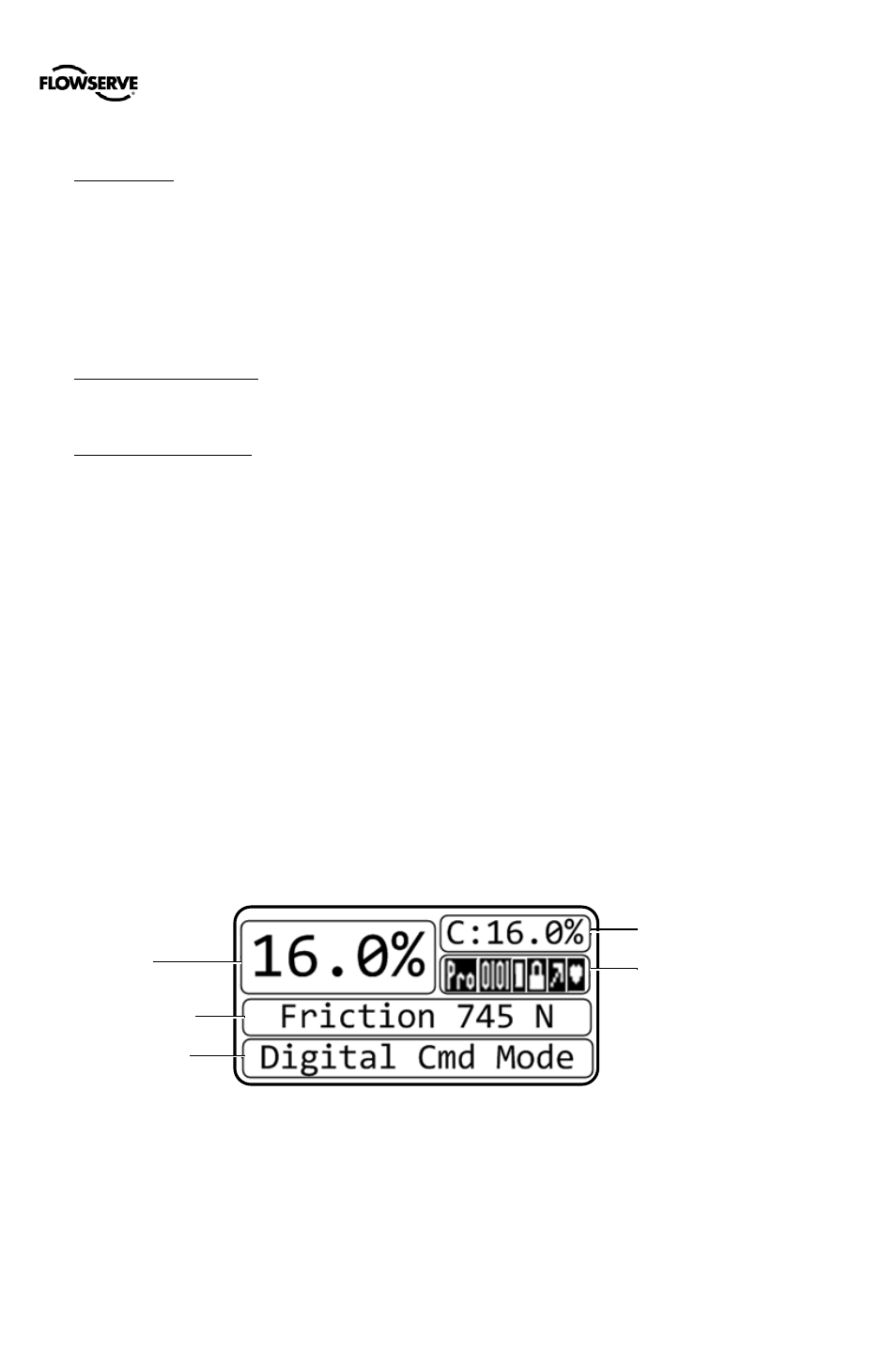
Final Command
Status Icon
Position
Scrolling Status
Message
Current Alarm
Status
Figure 33: Display Main View