3 mounting to standard valtek rotary valves, Ounting to, Tandard – Flowserve 500+ Series Logix User Manual
Page 15: Altek, Otary, Alves
User Instructions - Logix® 500+ Series Digital Positioners FCD LGENIM0105-10 11/13
flowserve.com
15
5.3
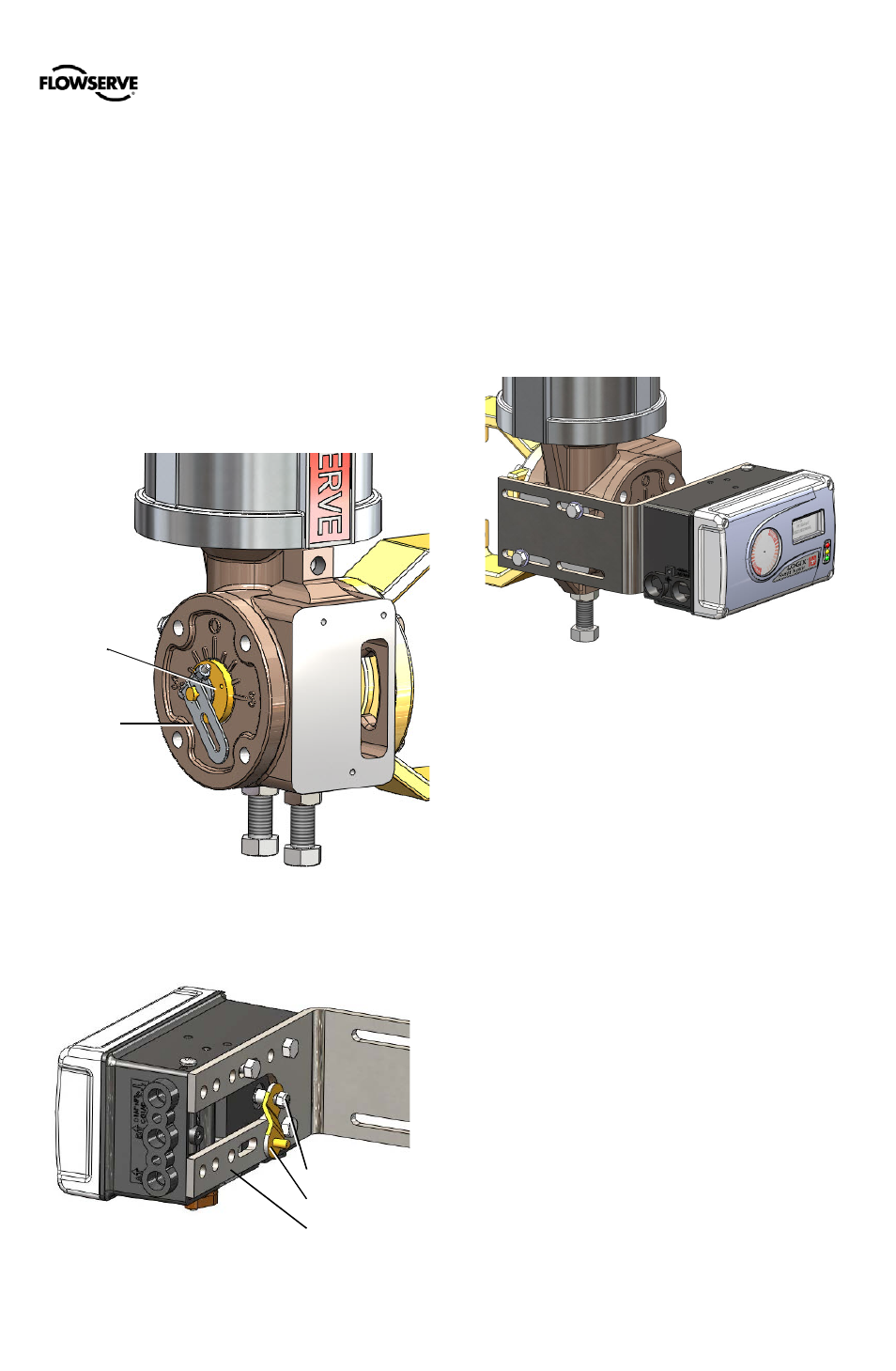
Mounting to Standard Valtek Rotary
Valves
The standard rotary mounting applies to Valtek
valve/actuator assemblies that do not have mounted volume
tanks or hand-wheels. The standard mounting uses a linkage
directly coupled to the valve shaft. This linkage has been
designed to allow for minimal misalignment between the
positioner and the actuator.
1
Fasten the spline lever adapter to the splined lever
using two 6 x 1/2" self-tapping screws.
2
Slide the take-off arm onto the spline lever adapter
shaft, orienting the arm to the current valve position.
Insert the screw with star washer through the take-off
arm and add the second star washer and nut and
tighten.
3
Attach follower arm to positioner feedback shaft using
the star washer and 10-32 nut.
4
Rotate the follower arm so the follower pin will slide into
the slot on the take-off arm. Adjust the bracket position
as needed noting the engagement of the follower pin
and the take-off arm slot. The pin should extend
approximately 2 mm past the take-off arm. When
properly adjusted, securely tighten the bracketing bolts
5
Using four 1/4-20 x 1/2" bolts, fasten positioner to
universal bracket using appropriate hole pattern
(stamped on bracket).
6
7
Using a ½” end wrench and two 5/16-18 X ½” bolts,
attach bracket to actuator transfer case pad. Leave
these bolts slightly loose until final adjustments are
made.
8
Rotate follower arm so the follower pin will slide into the
slot on the take-off arm. Over-rotate the follower arm if
needed so the arm moves freely through the intended
travel.
NOTE: The feedback shaft has a clutch mechanism that
allows for over-rotation of the shaft for easy adjustments.
9
Adjust the bracket position as needed noting the
engagement of the follower pin and the take-off arm
slot. The pin s
hould extend approximately 1⁄16" past the
take-off arm. When properly adjusted, securely tighten
the bracketing bolts.
10
Connect regulated air supply to appropriate port in
manifold. See section 6 TUBING.
11
Connect the power to the 4-20 mA terminals. See
section 7 ELECTRICAL CONNECTIONS.
12
Remove main cover and locate DIP switches and
QUICK-CAL/ACCEPT button.
13
Refer to sticker on main board cover and set DIP
switches accordingly. See section 8 STARTUP.
14
Press the QUICK-CAL/ACCEPT button for three to four
seconds or until the positioner begins to move. The
positioner will now perform a stroke calibration.
15
If the calibration was successful the green LED will blink
GGGG or GGGY and the valve will be in control mode.
16
If calibration fails, as indicated by a RGGY blink code,
retry the calibration. If it still fails, the feedback values
Figure 8: Valtek Rotary Take-Off Arm
Spline
Lever
Adapter
Take-Off
Arm
Assembly
Figure 9: Valtek Rotary Follower Arm
Follower Arm
Feedback Shaft
Universal
Bracket
Figure 7: Valtek Rotary Mounting