13 multi-function card, 1 analog output (ao), 2 discrete output (do) – Flowserve 500+ Series Logix User Manual
Page 41: 3 discrete input (di), Multi-function card, Nalog, Utput, Iscrete, Nput
User Instructions - Logix® 500+ Series Digital Positioners FCD LGENIM0105-10 11/13
flowserve.com
41
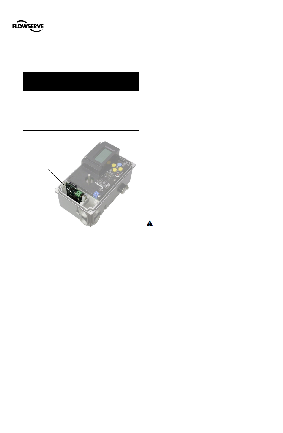
13 MULTI-FUNCTION CARD
The optional Multi-Function Card (MFC) can be configured to
act as an Analog Output, Discrete Output, or Discrete Input.
Up to two MFCs may be installed at one time. MFCs are
immune to RFI/EMI disturbances. See certifications in
section
Table 21: Multi-Function Card Cross-References
Information
IOM Section
Analog Output
Specifications
Electronic
Connections
7.3 Multi-Function Card (AO, DO, DI)
Configuration
Certifications
3 Hazardous Area Certifications
Status
Table 13: Auxiliary Card Status
Figure 37: Multi-Function Card
13.1 Analog Output (AO)
Configure the MFC as an Analog Output device to produce a
4-20 mA signal that corresponds to the position of the valve.
Output follows actual position of valve, including all failure
modes of positioner except loss of power. An output of < 1.0
mA is transmitted when the positioner loses power.
Calibration of the analog output signal is performed using the
display menu, a HART handheld communicator, or the
ValveSight DTM .
The MFC configured as an AO does not interfere with
positioner operation.
NOTE: The AO signal corresponds with the Signal At
Closed configuration switch setting. If the valve closes with
a 4 mA signal, the AO will show a 4 mA signal when closed.
If the valve closes with a 20 mA signal, the AO will show a 20
mA signal when closed.
13.2 Discrete Output (DO)
Use the Discrete Output function of the MFC to indicate a
variety of conditions such as alarms, warnings, position
limits, etc. Alarms that are masked will not cause the DO to
trip. The current is normally high, and drops low when one of
the pre-configured states occurs.
Configuration of the discrete output signal is done using the
ValveSight DTM.
The MFC configured as a DO does not interfere with
positioner operation.
The MFC DO complies with DIN 19234 standard. For
specific current limits, see Table 13: Auxiliary Card Status.
13.3 Discrete Input (DI)
Use the Discrete Input function of the MFC to signal the
positioner to begin a partial stroke test, or move to a
predefined position as long as the signal remains.
Supply a low voltage (or no voltage) to indicate a normal
state. Raise the voltage to indicate the tripped state.
Configuration of the discrete output signal is done using the
display menu, a HART handheld Communicator, or the
ValveSight DTM .
For specific voltage limits, see Table 13: Auxiliary Card
Status.
NOTE: When 2 cards are configured as DI at the same
time, where both are configured to override the position
command, the card in slot 1 will take priority regardless of the
order in which the override commands are triggered.
CAUTION: During the use of the Discrete Input function,
the valve may stroke unexpectedly. Follow internal
procedures, ensuring that the configured movement of the
valve (performing a PST or moving to a set-point) is allowed.
Notify proper personnel that the valve will stroke, and make
sure the valve is properly isolated if required.
Multi-
Function
Card