4 limit switches, 5 remote mount, 6 connections for intrinsically safe operation – Flowserve 500+ Series Logix User Manual
Page 25: Imit, Witches, Emote, Ount, Onnections for, Ntrinsically, Peration
User Instructions - Logix® 500+ Series Digital Positioners FCD LGENIM0105-10 11/13
flowserve.com
25
7.4
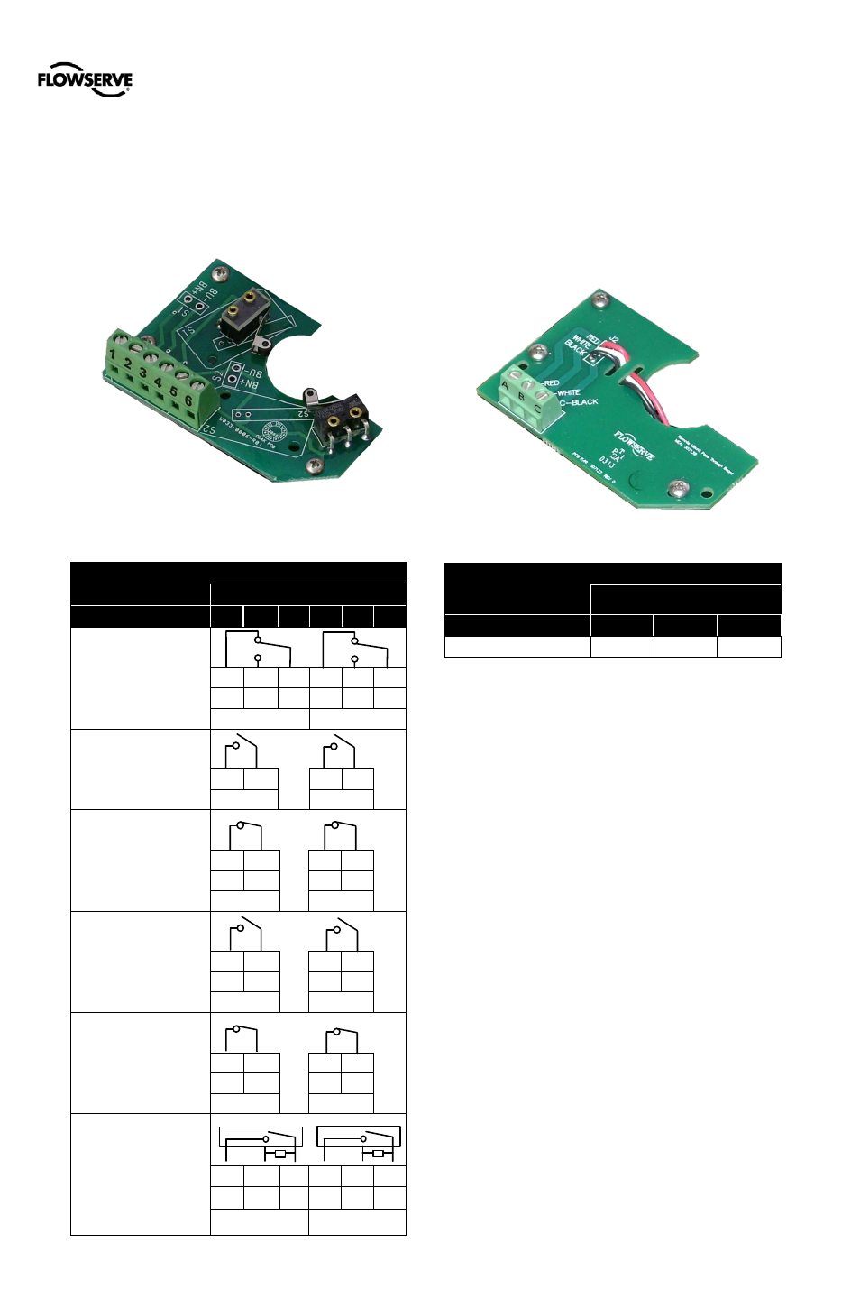
Limit Switches
Limit switches provide an independent verification of the
position of the feedback shaft. Wire the limit switches
according to Table 14: Limit Switch Connections. For more
information, see Table 7: Limit Switch Specifications on page
9.
Figure 29: Limit Switch Board
Table 14: Limit Switch Connections
Terminal (See Figure 29)
Switch
1
2
3
4
5
6
Mechanical
Cherry DG 13-B2RA
1 & 4 NC
NC NO
C
NC NO
C
+
+
-
+
+
-
LS1
LS2
Reed
Hamlin 59165-1-S-00-C
NO
+
-
+
-
LS1
LS2
Inductive Sensor
P&F NJ2-V3-N
NAMUR NC
BN
BU
BN BU
+
-
+
-
LS1
LS2
Inductive Proximity
P&F SJ2-S1N
BN
BU
BN BU
NAMUR NO
+
-
+
-
LS1
LS2
Inductive Proximity
P&F SJ2-SN
BN
BU
BN BU
NAMUR NC
+
-
+
-
LS1
LS2
Inductive Sensor
P&F NBB2-V3-E2
PNP NO
BN
BU
BK BN BU
BK
General Purpose Only Vcc+
-
SW+ Vcc+
-
SW+
LS1
LS2
7.5
Remote Mount
The remote mount option can be used where excessive
vibration or environmental factors prevent the placement of a
positioner directly on the valve. Wire the remote mount
board according to Table 15: Remote Mount Card
Connections. For more information, see Table 6: Remote
Mount Specifications on page 8.
Figure 30: Remote Mount Board
Table 15: Remote Mount Card Connections
Terminal (See Figure 30:
A
B
C
From Remote Mount
Red
White
Black
7.6
Connections for Intrinsically Safe
Operation
See section 3 HAZARDOUS AREA CERTIFICATIONS for
entity parameters and control drawing reference.
LS1
LS2
Terminals
Terminals