5 replacing the lcd board, 6 replacing an auxiliary card, Eplacing the – Flowserve 500+ Series Logix User Manual
Page 46: Oard, Eplacing an, Uxiliary
User Instructions - Logix® 500+ Series Digital Positioners FCD LGENIM0105-10 11/13
flowserve.com
46
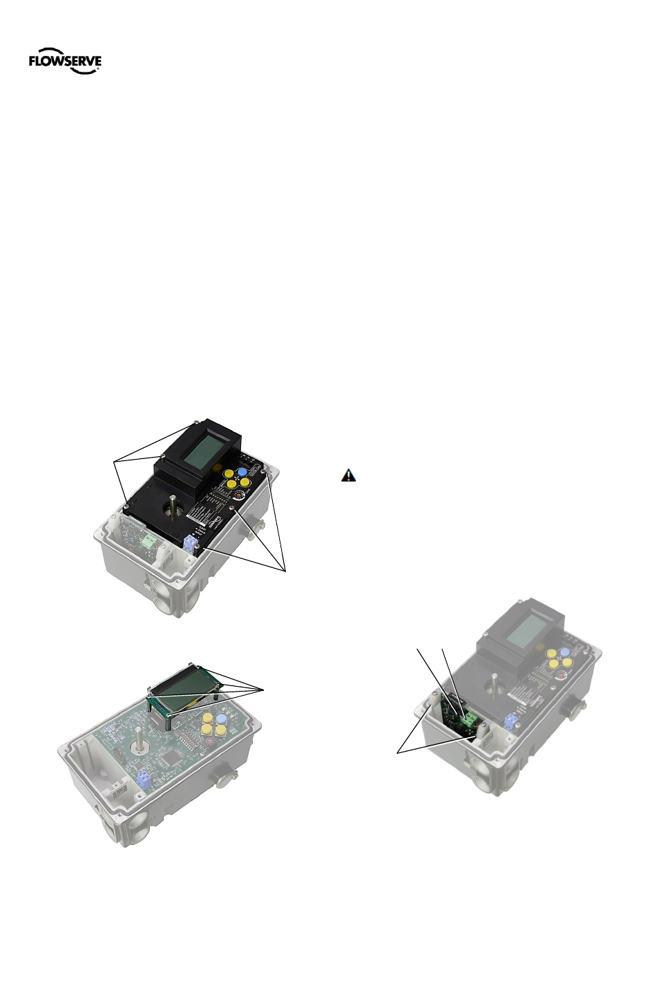
17.5 Replacing the LCD Board
The LCD board connects to the main board providing
additional functionality at the local user interface.
Removal
1
Make sure the valve is bypassed or in a safe condition.
2
Disconnect power to the positioner.
3
Remove the inner cover by removing the 6 inner cover
retaining screws.
4
Unscrew the 4 screws holding the LCD Board in place.
5
Gently pry the locking feature on the connector with a
small flat screwdriver and separate the connector from
the main board. Be careful not to pull the cable, as this
may cause damage to the cable.
Installation
1
Connect the LCD Board to the Main Board using the
cable. Ensure the connector’s locking features engage.
2
Align the LCD Board with the 4 stand-offs on the main
board.
3
Screw the LCD Board to the 4 stand-offs.
4
Replace the Inner Cover.
NOTE: The LCD backlight may change brightness during
use. This is normal. The backlight uses any residual power
not used by other functions of the circuitry. When current
supply is low (4mA) the light will appear darker. When
current supply is high (20mA) the light will appear brighter.
Figure 42: Inner Cover
Figure 43: LCD
17.6 Replacing an Auxiliary Card
Up to two auxiliary cards can be installed at a time. Each
communicates independently to the main processor, though
only one cable is used to connect both cards.
Removal
1
Make sure the valve is bypassed or in a safe condition.
2
Disconnect the power to the positioner.
3
Remove the main cover.
4
Disconnect the two wire connection from the side of the
Card.
5
Unscrew and remove the auxiliary card clips.
6
Gently slide the card from the slot. (If two cards are
present, remove both cards from the slots.)
7
Gently pry the locking feature on the connector with a
small flat screwdriver and separate the connector from
the card. Be careful not to pull the cable, as this may
cause damage to the cable.
8
Replace the second card (if present) back into the slot.
9
Replace the auxiliary card clips.
Installation
1
Make sure the valve is bypassed or in a safe condition.
2
Disconnect the power to the unit.
3
Remove the main cover.
4
Unscrew and remove the auxiliary card clips.
5
If a card is present, gently slide the card from the slot to
access the internal connector.
6
Connect the card to the main board using the internal
connector cable. Ensure the connector’s locking
features engage.
7
Gently slide the card(s) into the slot(s).
CAUTION: Ensure proper circuitry is used before
connecting cables to the auxiliary card. See section 7
ELECTRICAL CONNECTIONS for more information.
8
Route the external cable through the electrical conduit
ports in the base and connect the external cable to the
auxiliary card. See Figure 37: Multi-Function Card.
9
Replace the auxiliary card clips.
10
Reinstall the main cover.
Figure 44: Auxiliary Card
Auxiliary
Card Clips
Auxiliary Card
Terminals
+ -
LCD
Screws
Inner
Cover
Screws
Inner
Cover
Screws