5 mounting to rotary namur (automax) valves, Ounting to, Otary – Flowserve 500+ Series Logix User Manual
Page 18: Namur, Alves
User Instructions - Logix® 500+ Series Digital Positioners FCD LGENIM0105-10 11/13
flowserve.com
18
5.5
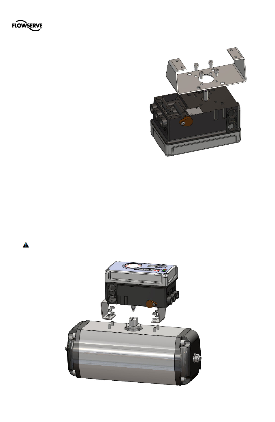
Mounting to Rotary NAMUR
(AutoMax) Valves
1
Attach the mounting plate to the positioner using 4
screws.
2
Rotate the feedback shaft to match the orientation of
the receiver on the actuator.
NOTE: The feedback shaft has a clutch mechanism that
allows for over-rotation of the shaft for easy adjustments.
3
Mount the positioner onto the actuator using the
washers and nuts.
4
Connect regulated air supply to appropriate port in
manifold. See section 6 TUBING.
5
Connect the power to the 4-20 mA terminals. See
section 7 ELECTRICAL CONNECTIONS.
6
Remove main cover and locate DIP switches and
QUICK-CAL/ACCEPT button.
7
Refer to sticker on main board cover and set DIP
switches accordingly. See section 8 STARTUP.
8
Press the QUICK-CAL/ACCEPT button for three to four
seconds or until the positioner begins to move. The
positioner will now perform a stroke calibration.
9
If the calibration was successful the green LED will blink
GGGG or GGGY and the valve will be in control mode.
10
If calibration fails, as indicated by a RGGY blink code,
retry the calibration. If it still fails, remove power from
the positioner, disconnect the air, and remove the
positioner from the actuator. Rotate the feedback shaft
so that the full free travel of the feedback shaft is in the
range of the actuator movement. Optionally, continue
to attempt the calibration. Each calibration attempt
adjusts the acceptable limits and it should pass
eventually.
CAUTION: Remember to remove the air supply before
re-adjusting take-off arm.
Figure 15: AutoMax Bracket
Figure 16: AutoMax Assembly