13 inner loop, 14 detailed sequence of positioner operations, 15 inner loop offset – Flowserve 500+ Series Logix User Manual
Page 6: Nner, Etailed, Equence of, Ositioner, Perations, Ffset
User Instructions - Logix® 500+ Series Digital Positioners FCD LGENIM0105-10 11/13
flowserve.com
6
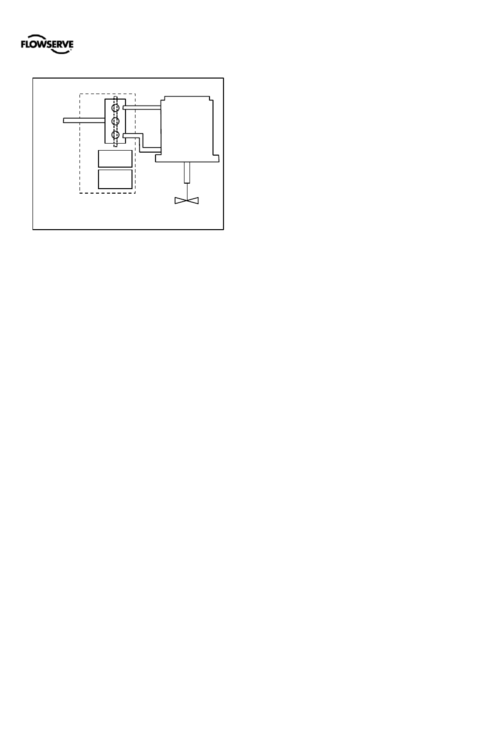
1.13 Inner Loop
The inner-loop controls the position of the relay valve by
means of a driver module. The driver module consists of a
temperature-compensated hall-effect sensor and a Piezo
valve pressure modulator. The Piezo valve pressure
modulator controls the air pressure under a diaphragm by
means of a Piezo beam bender. The Piezo beam deflects in
response to an applied voltage from the inner-loop
electronics. As the voltage to the Piezo valve increases, the
Piezo beam bends, closing off against a nozzle causing the
pressure under the diaphragm to increase. As the pressure
under the diaphragm increases or decreases, the spool or
poppet valve moves up or down respectively. The Hall Effect
sensor transmits the position of the spool or poppet back to
the inner-loop electronics for control purposes.
1.14 Detailed Sequence of Positioner
Operations
A more detailed example explains the control function.
Assume the unit is configured as follows:
•
Unit is in Analog command source.
•
Custom characterization is disabled (therefore
characterization is Linear).
•
No soft limits enabled. No MPC set.
•
Valve has zero deviation with a present input signal of
12 mA.
•
Loop calibration: 4 mA = 0% command, 20 mA = 100%
command.
•
Actuator is tubed and positioner is configured air-to-
open.
Given these conditions, 12 mA represents a Command
source of 50 percent. Custom characterization is disabled so
the command source is passed 1:1 to the Final Command.
Since zero deviation exists, the stem position is also at 50
percent. With the stem at the desired position, the spool
valve will be at a middle position that balances the pressures
above and below the piston in the actuator. This is commonly
called the null or balanced spool position.
Assume the input signal changes from 12 mA to 16 mA. The
positioner sees this as a command source of 75 percent.
With Linear characterization, the Final Command becomes
75 percent. Deviation is the difference between Final
Command and Stem Position: Deviation = 75% - 50% =
+25%, where 50 percent is the present stem position. With
this positive deviation, the control algorithm sends a signal to
move the spool up from its present position. As the spool
moves, the supply air is applied to the bottom of the actuator
and air is exhausted from the top of the actuator. This new
pressure differential causes the stem to start moving towards
the desired position of 75 percent. As the stem moves, the
Deviation begins to decrease. The control algorithm begins to
reduce the spool opening. This process continues until the
Deviation goes to zero. At this point, the spool will be back in
its null or balanced position. Stem movement will stop and
the desired stem position is now achieved.
1.15 Inner Loop Offset
The position of the spool (or poppet) at which the pressures
are balanced, holding the valve position in a steady state, is
called the Inner Loop Offset. The controlling algorithm uses
this value as a reference in determining the Piezo voltage.
This parameter is important for proper control and is
optimized and set automatically during stroke calibration.
Piezo
Valve
Hall
Sensor
Air
Supply
Spool
Valve
Double Acting
Pilot Relay
Control
Valve
Actuator
Figure 2: Double Acting Relay Operation