5 electromagnetic compatibility, 3 multi-function card (ao, do, di), 1 analog output – Flowserve 500+ Series Logix User Manual
Page 24: 2 discrete output, 3 discrete input, Ulti, Unction
User Instructions - Logix® 500+ Series Digital Positioners FCD LGENIM0105-10 11/13
flowserve.com
24
7.2.5
Electromagnetic Compatibility
The Logix 500+ digital positioner has been designed to
operate correctly in electromagnetic (EM) fields found in
typical industrial environments. Care should be taken to
prevent the positioner from being used in environments with
excessively high EM field strengths (greater than 10 V/m).
Portable EM devices such as hand-held two-way radios
should not be used within 30 cm of the device.
Ensure proper wiring and shielding techniques of the control
lines, and route control lines away from electromagnetic
sources that may cause unwanted electrical noise. An
electromagnetic line filter can be used to further eliminate
noise (FLOWSERVE Part Number 10156843).
In the event of a severe electrostatic discharge near the
positioner, the device should be inspected to ensure correct
operability. It may be necessary to recalibrate the Logix 500+
positioner to restore operation.
7.3
Multi-Function Card (AO, DO, DI)
The Multi-Function Card can act as an Analog Output (AO), a
Discrete Output (DO), or a Discrete Input (DI). Connections
to the Multi-Function Card are made directly to the card
terminals. For detailed information about voltage and current
limits, see Table 13: Auxiliary Card Status below.
See section 13 MULTI-FUNCTION CARD for more
information.
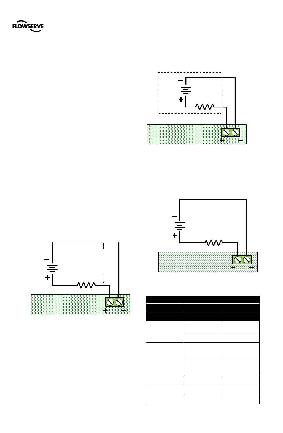
7.3.1
Analog Output
For AO function wire the MFC in series with a 10 to 40 VDC
power supply, including a method to determine the current.
When configured as an AO, the current will follow the valve
position.
Figure 26: MFC Analog Output Circuit
7.3.2
Discrete Output
For DO function, wire the MFC in series with a 8 to 40 VDC
power supply, including a method to determine the current
such as a resistor. Or use a NAMUR switch amplifier made
for this purpose. In DO configuration, the card is a NAMUR
switch.
When configured as a DO, current will remain high until the
user-defined condition (an alarm) is active, and then drop low
when tripped.
Figure 27: MFC Discrete Output Circuit
7.3.3
Discrete Input
For the DI function, wire the MFC in series with a 0 to 40
VDC power supply. Keep the voltage low under normal
circumstances. Raise the voltage to create a tripped input
state.
Figure 28: MFC Discrete Input Circuit
Table 13: Auxiliary Card Status
Card
Condition
Status Indication
Multi-Function Card
MFC (AO)
Monitoring Position
(typical 4-20mA )
Output (mA)
Less than 8 V on
AO terminals.
No Loop Power
MFC (DO)
High
(output > 2.1 mA)
(typically 3 mA)
1 - Nominal
Low
(1.2 mA > output >
0.1 mA)
(typically 0.5 mA)
0 - Tripped
Less than 0.1 mA
No Loop Power
MFC (DI)
Low
(input < 2.5 VDC)
1 - Nominal
High
(input > 8.0 VDC)
0 - Tripped
10 VDC
to
40 VDC
Voltage
Source
MFC
8 VDC
Minimum
MFC
0 VDC
to
40 VDC
Voltage
Source
MFC
Discrete Input
Voltage Loop
(Logix Input)
1 k
Ω
Typical
Switch Amp