6 tubing, 1 determine air action, 2 connect supply port – Flowserve 500+ Series Logix User Manual
Page 20: 3 purging single acting actuators, Tubing, Etermine, Ction, Onnect, Upply, Urging
User Instructions - Logix® 500+ Series Digital Positioners FCD LGENIM0105-10 11/13
flowserve.com
20
6 TUBING
After mounting has been completed, tube the positioner to
the actuator using the appropriate compression fitting
connectors. For best performance, use 10 mm (3/8 inch)
tubing for 645 square cm (100 square inch) actuators or
larger.
6.1
Determine Air Action
The port labeled “Y1” delivers air when an air supply is
present and the relay is energized. (For positioners with
double acting relays, this is port A. For positioners with
single acting relays, this is port B.) Typically, the port labeled
“Y1” should be tubed to the pneumatic side of the actuator
(the side that would result in the air compressing the actuator
spring). When tubed this way, the spring is designed to
return the valve to the fail safe state should supply air or
power to the unit fail.
Tube the port labeled “Y1” to the side of the actuator that
must receive air to begin moving away from the fail safe
state.
If air from “Y1” should open the valve, set the Air Action
configuration switch on the positioner to Air-to-Open,
otherwise set it to Air-to-Close.
The Air-to-Open and Air-to-Close selection is determined by
the actuator tubing, not the software. When air action
selection is made during configuration, the selection tells the
control which way the actuator has been tubed.
If the valve is double acting, port the valve labeled “Y2” to the
other side of the actuator.
DANGER: Proper tubing orientation is critical for the
positioner to function correctly and have the proper failure
mode.
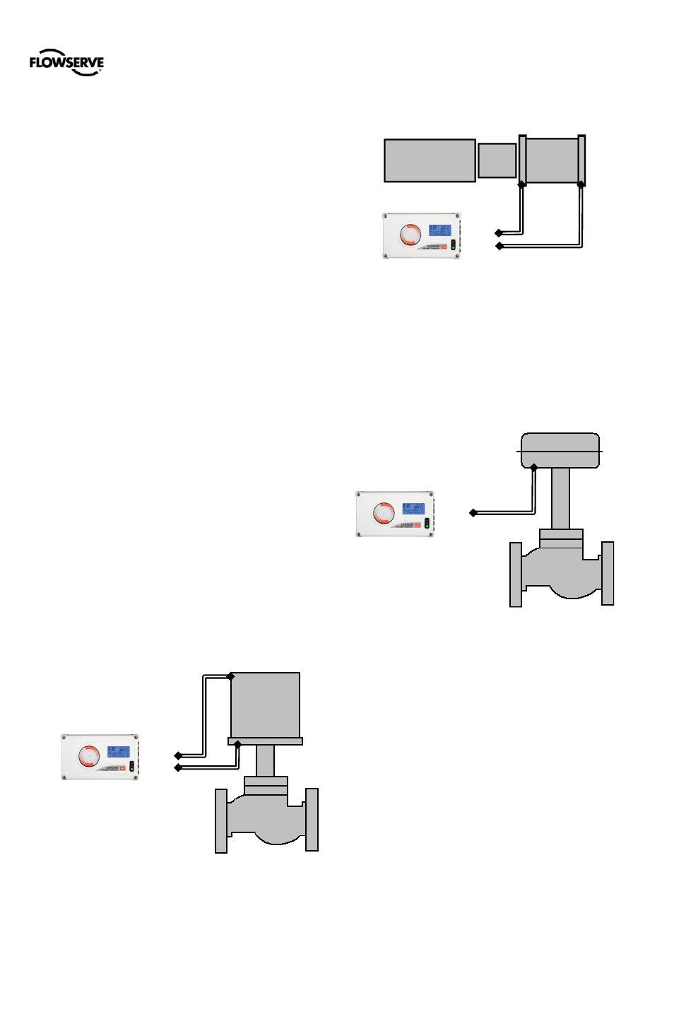
Example: Tubing Linear Double-Acting Actuators
For a linear air-to-open actuator, the “Y1” port of the
positioner is tubed to the bottom side of the actuator (closest
to the valve). The “Y2” port of the positioner is tubed to the
top side of the actuator. For a linear air-to-close actuator the
tubing configuration is reversed.
Figure 18: Tubing Linear, Double Acting, Air to Open
Example: Tubing Rotary Double-Acting Actuators
For a rotary actuator, the “Y1” port of the positioner manifold
is tubed to the far side of the actuator. The “Y2” port of the
positioner manifold is tubed to the side of the actuator closer
to the transfer case. This tubing convention is followed
regardless of air action. On rotary actuators, the transfer
case orientation determines the air action.
Figure 19: Tubing Rotary, Double Acting, Air to Open
Example: Tubing Single-acting Actuators
For single-acting actuators, the “Y1” port is always tubed to
the pneumatic side of the actuator regardless of air action. If
a double acting (spool style) relay is installed in the
positioner, plug port B (Y2). If a single acting - poppet style
relay is installed, plug port A (Y2). Or, port A may be used
for purging. See Purging Single Acting Actuators below.
Figure 20: Tubing Linear, Single Acting, Air to Open
6.2
Connect Supply Port
The positioner ports are threaded with either G ¼ or ¼
NPTF as indicated on the housing.
In order to maintain the recommended air quality, a
coalescing filter should always be installed in the supply gas
line. An air filter is highly recommended for all applications
where dirty air is a possibility. The positioner passage ways
are equipped with small filters, which remove medium and
coarse size dirt from the pressurized air. If necessary, they
are easily accessible for cleaning.
A supply regulator is recommended if the customer will be
using the diagnostic features of the Logix 500+ but is not
required. In applications where the supply pressure is higher
than the maximum actuator pressure rating a supply
regulator is required to lower the pressure to the actuator’s
maximum rating.
6.3
Purging Single Acting Actuators
Purging allows the non-pressurized side of a single acting
actuator to fill with exhaust gas instead of atmospheric air.
This configuration helps prevent corrosion of actuator
components in harsh environments. When a single acting
S
B (Y2)
A (Y1)
Spool Relay
S
B (Y2)
A (Y1)
Spool Relay
S
B (Y1)
A (Y2) Plug
Poppet Relay