Flowserve 500+ Series Logix User Manual
Page 7
Advertising
User Instructions - Logix® 500+ Series Digital Positioners FCD LGENIM0105-10 11/13
flowserve.com
7
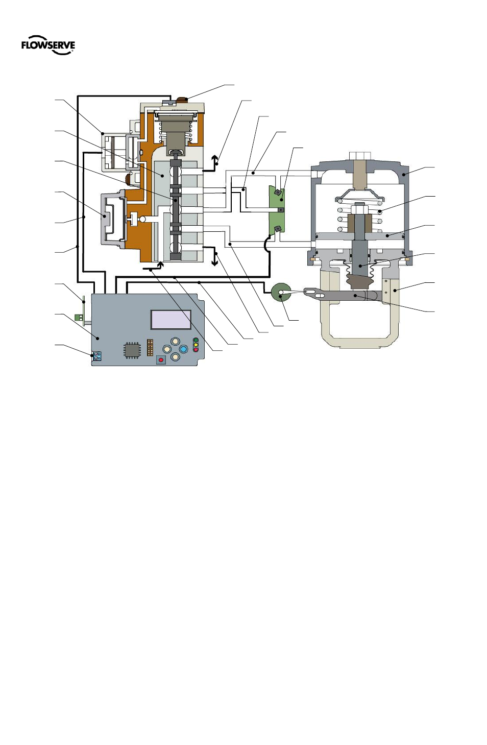
(Double Acting Relay - Air To Open)
Figure 3:
Logix 500+ Digital Positioner Schematic
1 - Piezo Assembly
2 - Block
3 - Spool
4 - Regulator Assembly
5 - Piezo Cable
6 - Hall Sensor Cable
7 - Auxiliary Card
8 - Main Board
9 - 4-20 mA Input
1
2
3
4
5
6
8
10
9
7
11
12
13
14
22
21
23
24
25
15
16
17
18
19
20
26
15- Supply In
16- Pressure Sensor Cable
17- Feedback Cable
18- Exhaust
19- Port A
20- Feedback Potentiometer
10- Hall Sensor Assembly
11- Exhaust
12- Port B
13- Supply Pressure
14- Pressure Sensor Board
21- Actuator Housing
22- Spring
23- Piston
24- Stem
25- Yoke
26- Take-Off Arm
Advertising