Fluke Biomedical ESA612 User Manual
Page 32
ESA612
Users Manual
18
To perform a ground wire resistance test:
1. Ensure the power cord from the DUT is plugged into
the Analyzer’s test receptacle.
2. Press
to reveal the resistance function menu.
3. Connect one end of a test lead to the V/
Ω
/A jack as
shown in Figure 10.
4. If using an accessories probe, connect it to the other
end of the test lead and place the probe tip into the
∅
/Null
jack. If using an alligator clip accessory,
connect it to the other end of the test lead, place the
null post adapter in the
∅
/Null
jack, and clamp the
alligator clip to the null post adapter.
5. Connect the other end of the test lead to
∅
/Null
jack.
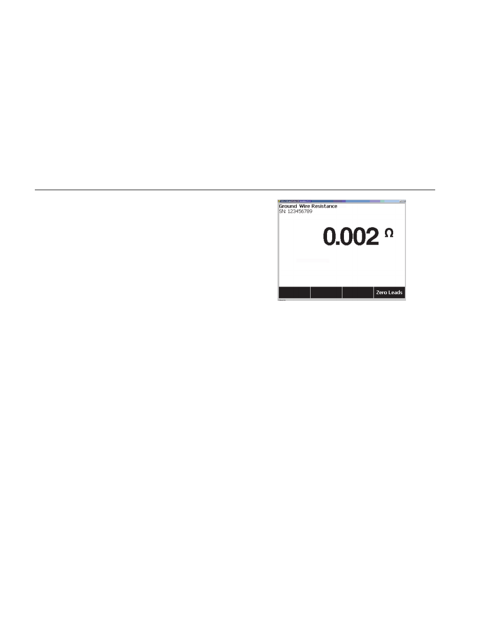
6. Press the softkey labeled Zero Leads. The Analyzer
zeroes out the measurement to cancel the test lead
resistance.
7. Connect the test lead coming from the
∅
/Null
jack to
the DUT enclosure or protective earth connection.
8. The measured resistance is displayed as shown in
Figure 9 after the DUT connection(s) is/are made.
fis105.jpg
Figure 9. DUT Ground Resistance Measurement
Warning
To avoid electric shock, remove the null post
adapter from the
∅
/Null jack after a test lead
zero is performed. The
∅
/Null jack becomes
potentially hazardous during some of the test
conditions.