Post-startup tests – Gasboy 70 Series User Manual
Page 24
GASBOY Series 70 & 1820
4-2
MDE-4423B Series 70 and 1800 Consumer Elect Pumps Installation/Operation/Parts
●
July 2005
POST-STARTUP TESTS
Voltage
The incoming voltage to the pump should be checked and any reading not within 10% of rated
voltage should be corrected before testing is continued. When dealing with suction pumps, it is
good practice to take voltage readings while the suction pump is operating on bypass (turned on
but not dispensing product) and also while making a delivery. Any voltage drop in excess of 10%
during either of these operating states should be considered a low voltage condition. Corrective
action should be taken to insure an adequate power supply to the pump.
Tightness
After determining that the pump is operating satisfactorily and the system is fully primed, check
the pump and piping to make sure that all connections are tight. We recommend that the tank
and all piping not be covered until this has been completed.
Meter Calibration
NOTE:
This meter was redesigned causing the calibration procedure to be different depending
on the age of your meter. Meters made after May 10,1995 are referred to as new style
meters; meters made before that date are referred to as old style.
All GASBOY pumps are adjusted for accurate measure for gasoline within + .05 gallons at the
factory. However, since the conditions of the installation can affect pump accuracy, it is the
responsibility of the installer to check the pump for accuracy and make any needed adjustments.
Where required, it is the owner's responsibility to report this device to the local Weights and
Measures officials for their inspection before the unit is put into service.
Choose the flow rate at which the meter will be used most often for the zero calibration point. For
example, if the pump is being used with an automatic nozzle, calibrate with the nozzle set on the
middle or top notch position, whichever is used most frequently.
Use a certified five-gallon measure with a sight glass and scale showing cubic-inches over or
under an exact five gallons. Fill and drain the test measure to completely wet the interior
surfaces. Reset the register to zero and deliver an exact measured five gallons into the test
measure at the selected flow. Read the level of the liquid in the sight glass on the scale in +
cubic-inches.
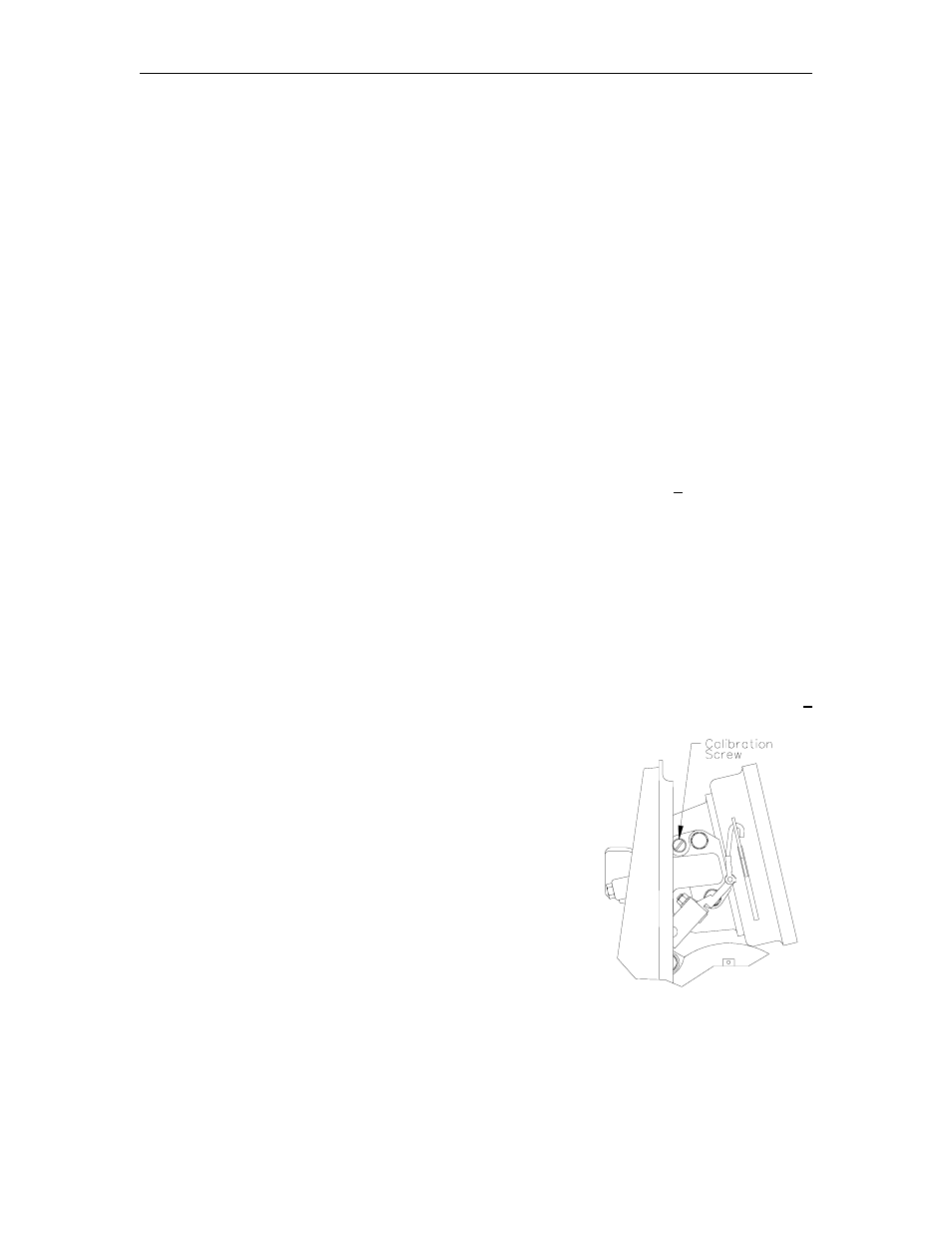
Follow the instructions in Section 3, Cabinet Removal for
Installation or Service to access the calibration screw. Use a
narrow blade screw driver to turn the adjusting screw clockwise
to correct for plus cubic-inches or counterclockwise for minus
cubic-inches in the test measure.
Count the number of full turns and fractional turns each time for
reference in judging the number and direction of any additional
turns required to calibrate the meter to exact zero.
For new style meters, start with the screw turned all the way in
clockwise. For gasoline calibration, turn the screw
approximately two full turns counter-clockwise. For diesel, turn
the screw approximately two full turns counter-clockwise.
Replace the cap screw (old style only). Deliver about 1/2 gallon through the meter before resetting
to zero and retesting. Allow a ten second drain period each time the test measure is emptied to
assure accurate measure. Adjust and retest until register is zeroed at desired flow.