Serial i/o board pcb5 - status indicators -24, Serial i/o board pcb5 - status indicators – Hypertherm HT4400 HySpeed Plasma Arc Cutting System User Manual
Page 115
MAINTENANCE
5-24
HT4400
Instruction Manual
3
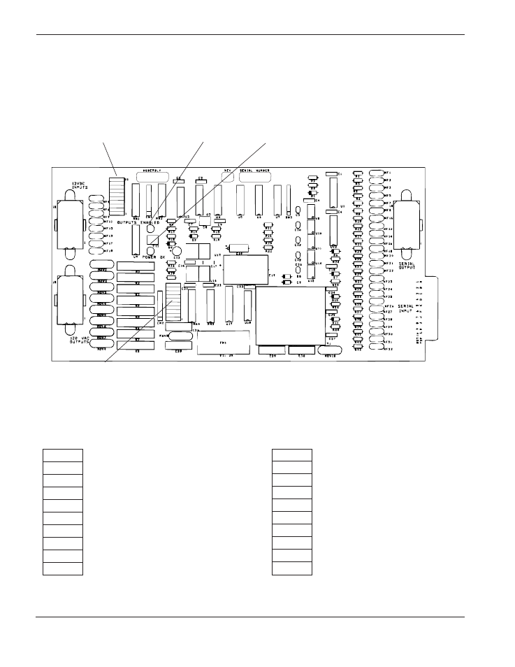
Serial I/O Board PCB5 - Status Indicators
The Serial I/O Board interfaces with the gas console and the microprocessor control board. The serial board
controls all outputs for the gas console. When an LED on LEDN1 or LEDN2 is illuminated, the corresponding
output or input is active. See page 6-2 for location of Serial I/O Board.
Note:
•
D2 needs to be illuminated for the outputs to be active.
•
If D5 is illuminated and D2 is not, then there is a communication problem between the
microprocessor control board (PCB2) and the serial board (PCB5).
•
LEDN1-5 through LEDN1-8 illuminate when in proper working conditions (no errors).
LEDN1-10
Not used
LEDN1-9
Not used
LEDN1-8
Shield cut-flow pressure switch (SC)
LEDN1-7
Plasma cut-flow pressure switch (PC)
LEDN1-6
Shield preflow pressure switch (SP)
LEDN1-5
Plasma preflow pressure switch (PP)
LEDN1-4
BCD1
LEDN1-3
BCD2
LEDN1-2
BCD4
LEDN1-1
BCD8
LEDN1
Input light bar
D2
Outputs Enabled
D5
+12 VDC
LEDN2
Output light bar
LEDN2-10
Not used
LEDN2-9
Not used
LEDN2-8
Nitrogen purge valve (SV-NP)
LEDN2-7
Secondary gas shield preflow (SV7)
LEDN2-6
Secondary gas shield cut-flow (SV6)
LEDN2-5
Secondary gas preflow (SV5)
LEDN2-4
Primary gas shield preflow (SV4)
LEDN2-3
Primary gas shield cut-flow (SV3)
LEDN2-2
Primary gas preflow (SV2)
LEDN2-1
Plasma cut-flow (SV1)
LEDN1
LEDN2
J2
P1
J1
J3