Hypertherm HT4400 HySpeed Plasma Arc Cutting System User Manual
Page 122

MAINTENANCE
HT4400
Instruction Manual
5-31
3
Phase Loss Detection Board PCB21 - Status Indicators and Operation
Operation
The phase loss detection circuit looks at the incoming voltage and verifies that the voltages between the 3-wire
inputs are within +/- 15% of each other.
• After contactor CON1 closes, opto-coupler U1 on PCB21 is activated, shorting pins 1&2 of PL1 together
and illuminating LED1.
• If LED1 does not illuminate:
• Verify that voltages across points A B and C, phase-to-phase are approximately 255 VAC. If voltages
are not within +/- 15%, LED1 will not illuminate. Check the incoming line voltage and the contacts on
CON1.
• Check PCB21 fuses F1-F3. If any of the fuses are open, then PCB21 is faulty.
• Check jumper on P2 and verify that the jumper is set for 265V.
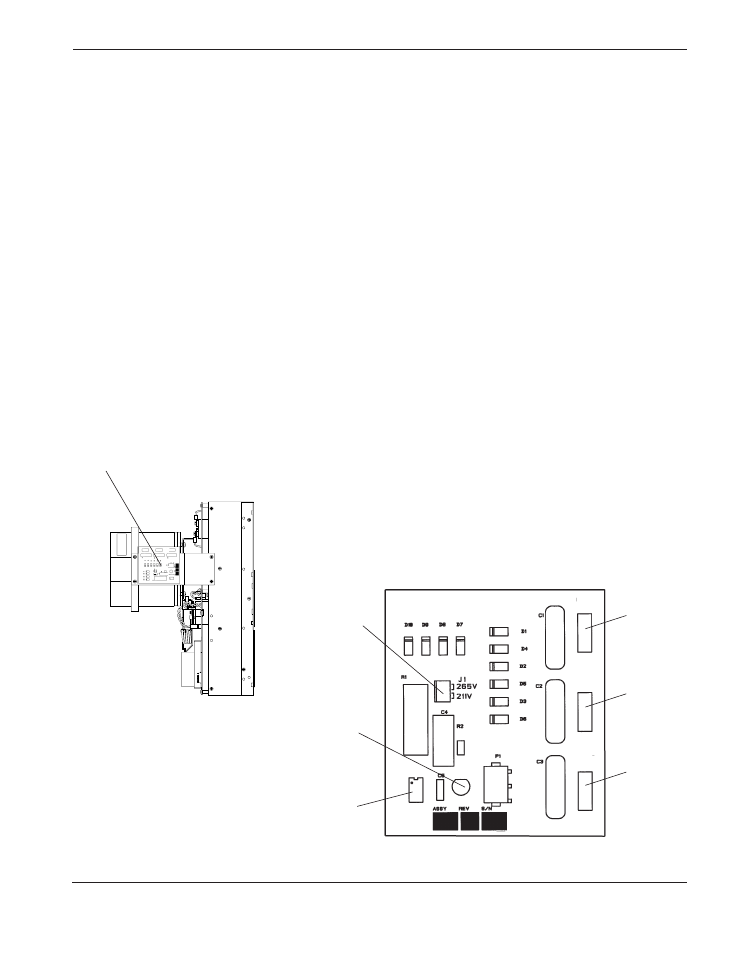
Phase Loss Board PCB21 location on chopper CH4 -
See page 6-3 for location of CH4
F1
A
F2
B
F3
U1
C
LED1
P2
P2 Jumper
for 265 V