2 construction of the hydraulic module, Construction of the hydraulic module – Nortec ME Control User Manual
Page 13
13
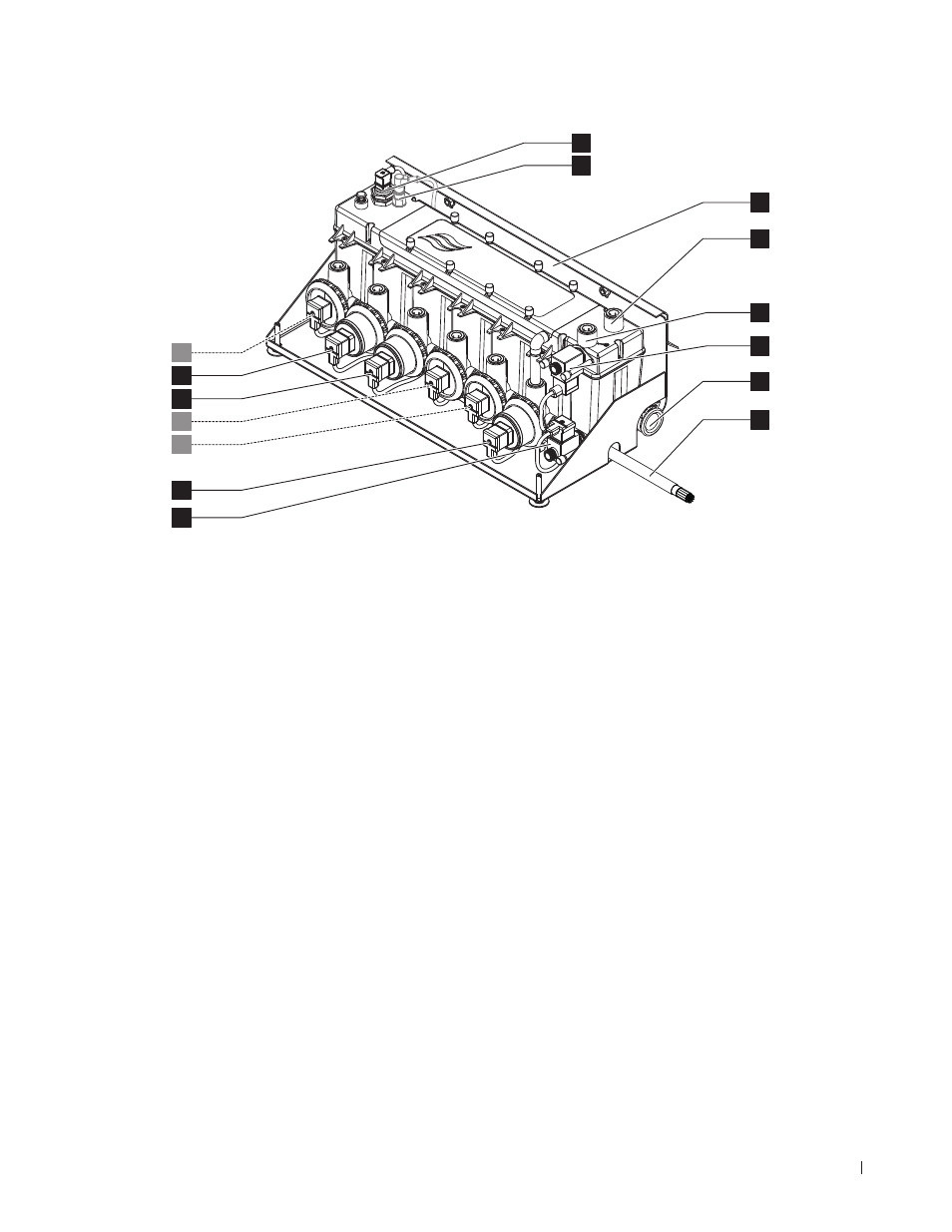
Product Overview
3.3.2 Construction of the hydraulic module
1 Drain valve (normally open)
2 Drain pump
3 Stage pump 5 with push-fit connector ø15 mm (0.625")
4 Stage pump 3 with push-fit connector ø15 mm (0.625")
5 Stage pump 1 with push-fit connector ø15 mm (0.625")
6 Stage pump 2 with push-fit connector ø15 mm (0.625")
7 Stage pump 4 with push-fit connector ø15 mm (0.625")
8 Level sensor
9 Conductivity sensor (option)
10 Fixing bracket
11 Push-fit connector ø15 mm (0.625") pressure equali-
sation (only used when mounted outside of AHU)
12 Water supply push-fit connector ø15 mm (0.625")
13 Inlet valve (normally closed)
14 Drain connector ø28 mm (1.125")
Note: drain connector can be turned 180° to drain
through the left or the right duct wall
15 Interconnecting cable hydraulic module
Fig. 3: Construction of the hydraulic module (figure shows layout for 2-stage control)
3
2
1
4
7
6
5
8
9
12
13
14
15
11
10