Installation & wiring, Important wiring considerations, Vcm-x modular e-bus controller technical guide 10 – Orion System VCM-X Modular E-BUS User Manual
Page 10: General, Controller mounting, Considerations
Zone
Zone
INSTALLATION & WIRING
VCM-X Modular E-BUS Controller Technical Guide
10
Warning: When using a single transformer to power more
than one controller or expansion module, the correct polarity must
always be maintained between the boards. Failure to observe correct
polarity will result in damage to the VCM-X E-BUS Controller
and expansion modules.
Please carefully read and apply the following information when wiring
the VCM-X E-BUS Controller or the Expansion Modules. See Figure
5 on page 11 for the VCM-X E-BUS Controller wiring diagram. See
Figures 16 and 17 on pages 19 and 20 for Expansion Module Wiring.
1. All wiring is to be in accordance with local and national
electrical codes and specifi cations.
2. Minimum wire size for 24 VAC wiring should be 18-gauge.
3. Minimum wire size for all sensors should be 24-gauge.
Some sensors require 2-conductor wire and some require
3-or 4-conductor wire.
4. Be sure that all wiring connections are properly inserted
and tightened into the terminal blocks. Do not allow wire
strands to stick out and touch adjoining terminals which
could potentially cause a short circuit.
5. When communication wiring is to be used to interconnect
VCM-X E-BUS Controllers together or to connect to other
communication devices, all wiring must be plenum-rated,
minimum 18-gauge, 2-conductor, twisted pair with shield.
WattMaster can supply communication wire that meets this
specifi cation and is color coded for the network or local
loop. Please consult your WattMaster distributor for
information. If desired, Belden #82760 or equivalent wire
may also be used.
6. Before applying power to the VCM-X E-BUS Controller,
be sure to recheck all wiring connections and terminations
thoroughly.
Important Wiring Considerations
General
Correct wiring of the VCM-X E-BUS Controller is the most important
factor in the overall success of the controller installation process. In
general, most VCM-X E-BUS Controllers are factory installed and wired
at the AAON
®
factory. It is also possible to purchase these controllers
through your local AAON
®
/Orion representative for installation in the
fi eld. Some of the following information pertains to fi eld wiring and
may not apply to your installation since it was pre-wired at the factory.
However, in the unlikely event that troubleshooting of the controller
is required, it is a good idea to be familiar with the system wiring, no
matter if it was factory or fi eld wired.
Controller Mounting
When the controller is to be fi eld mounted, it is important to mount
the controller in a location that is free from extreme high or low tem-
peratures, moisture, dust, and dirt. See Table 1 for a list of the required
operating conditions for the VCM-X E-BUS Controller and associated
expansion modules.
The VCM-X E-BUS Controller is housed in a plastic enclosure. It is
designed to be mounted by using the 3 mounting holes in the enclosure
base. The VCM-X E-BUS Controller needs to be installed in an envi-
ronment which can maintain a temperature range between -30°F and
150°F not to exceed 90% RH levels (non-condensing). It is important
to mount the controller in a location that is free from extreme high or
low temperatures, moisture, dust, and dirt. Be careful not to damage the
electronic components when mounting the controller.
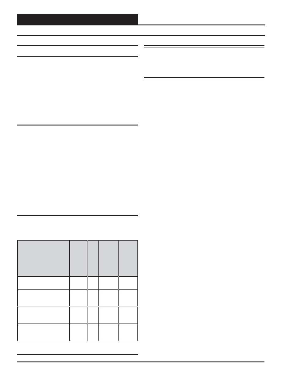
Considerations
The VCM-X E-BUS Controller and expansion modules must be con-
nected to a 24 VAC power source of the proper size for the calculated
VA load requirements. All transformer sizing should be based on the
VA rating listed in Table 1.
Contr
ol
De
vice
V
olta
ge
V
A
Load
Temper
atur
e
Humidity
(Non-
Condensing)
OE332-23E-VCMX
VCM-X E-BUS Controller
24VAC
8
-30°F to
150°F
90% RH
OE333-23-EM
VCM-X Expansion Module
24VAC
10
-30°F to
150°F
90% RH
OE358-23-12R
Relay Expansion Module
24VAC
15
-30°F to
150°F
90% RH
OE356-01-BI
4 Binary Expansion
Module
24VAC
5
-30°F to
150°F
90% RH
Table 1: Voltage and Environment Requirements