Installation & wiring, Building pressure control output wiring, Zone – Orion System VCM-X Modular E-BUS User Manual
Page 30: Figure 27: building pressure control output wiring, Vcm-x expansion module
Zone
Zone
INSTALLATION & WIRING
VCM-X Modular E-BUS Controller Technical Guide
30
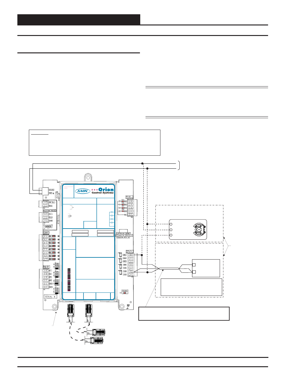
Building Pressure Control Output
The Building Pressure Control Output is a 0-10 VDC or 2-10 VDC signal
sent from the VCM-X Expansion Module. When using the output for
Direct Building Pressure Control (output signal rises on a rise in build-
ing pressure), the output signal can be connected to either a Variable
Frequency Drive controlling an exhaust fan or to a damper actuator
controlling an exhaust damper. When used in this manner, the output
signal must be confi gured for Direct Acting operation.
When using this output for Reverse Building Pressure Control (output
signal rises on a fall in building pressure), a damper actuator controlling
an OA Damper would be used. When using the OA damper for Reverse
Building Pressure Control, the output signal must be confi gured for
Reverse Acting operation. A Building Pressure Sensor connected to
AI4 on the VCM-X Expansion Module is used to sense and control the
signal to the Building Pressure Output. The OE258-01 Building Pressure
Sensor must be connected in order for the Building Pressure Output to
operate correctly.
See Figure 27 below for detailed wiring of the Building Pressure Control
Output Signal.
Caution:
Variable Frequency Drive units can cause large transient
noise spikes that can cause interference to be propagated on other
electronic equipment. Use shielded wire wherever possible and route
all sensor and controller wiring away from the Variable Frequency
Drive and the HVAC unit electrical wiring.
Figure 27: Building Pressure Control Output Wiring
Building Pressure Control Output Wiring
AO1
0-10 VDC Input From AO1
GND
GND
Shield
Shield
Modular Cable
Connect To VCM-X E-BUS
Controller
Modular Cable
Connect To Next Expansion
Board (When Used)
24 VAC
GND
10 VA Minimum Power
Required For
VCM-X Expansion Module
WARNING!!
Observe Polarity! All boards must be wired with GND-to-GND and 24VAC-to-24VAC.
Failure to observe polarity will result in damage to one or more of the boards. Expansion
Modules must be wired in such a way that the expansion modules and the controller are
always powered together. Loss of power to the expansion module will cause the controller
to become inoperative until power is restored to the expansion module.
24 V
A
C
GND
+
+
Building Pressure Control
Exhaust Fan Variable Frequency Drive
(By Others)
_
GND
Caution: The VFD Unit Must Be Configured
For 0-10VDC Input. The Input Resistance At
The VFD Must Not Be Less Than 1000 Ohms
When Measured At The VFD Terminals With
All Input Wires Removed.
Building Pressure Control
Damper Actuator
(By Others - Belimo Actuator Shown)
Wiring When Using Damper Actuator
For Building Pressure Control
Both Types Of
Building
Pressure
Control
Devices Are
Shown
Only One Type
Of Building
Pressure
Control Device
May Be Used
On Each HVAC
Wiring When Using Exhaust Fan VFD
For Building Pressure Control
3 Y1
2
1 - COM
Belimo Actuator
Wiring Shown.
Consult Factory For
Other Manufacturer
Wiring Instructions
+
VCM-X
Expansion
Module
Note:
Wire To The VFD Using 18 GA Minimum 2 Conductor Twisted
Pair With Shield Cable. Wire Shield To GND As Shown
RELAY CONTACT
RATING IS 1 AMP
MAX @ 24 VAC
RELAY 2
RELAY 1
RELAY 3
RELAY 4
RELAY
COMMON
I2C
EXPANSION
I2C
EXPANSION
AO1 = BUILDING PRESSURE CONTROL VFD OR
DAMPER ACTUATOR (0-10 OR 2-10 VDC)
= MODULATING HEATING SIGNAL
(0-10 VDC OR 2-10 VDC)
= MODULATING COOLING/DIGITAL SCROLL
SIGNAL (0-10 VDC, 2-10 VDC OR 1.5-5 VDC)
= RETURN AIR DAMPER ACTUATOR
(0-10 VDC)
= RETURN AIR BYPASS DAMPER ACTUATOR
(0-10 VDC)
= GROUND FOR ANALOG OUTPUTS
= GROUND FOR ANALOG OUTPUTS
AO2
AO3
AO4
AO5
GND
GND
BI1 = HOOD ON - N.O. INPUT
BI2
BI3
BI4
BI5
BI6
BI7
BI8
= DIRTY FILTER - N.O. INPUT
= PROOF OF FLOW - N.O. INPUT
= REMOTE FORCED OCCUPIED - N.O. INPUT
= REMOTE FORCED HEATING - N.O. INPUT
= REMOTE FORCED COOLING - N.O. INPUT
= SMOKE DETECTOR - N.C. INPUT
= REMOTE DEHUMIDIFICATION - N.O. INPUT
ANALOG INPUT
JUMPER SETTINGS
MUST BE SET AS
SHOWN FOR
PROPER
OPERATION
24 VAC POWER ONLY
WARNING! POLARITY MUST BE
OBSERVED OR THE BOARD
WILL BE DAMAGED
www.orioncontrols.com
AI1
AI2
AI3
AI4
THERM
THERM
THERM
THERM
4-20mA
4-20mA
4-20mA
4-20mA
0-10V
0-10V
0-10V
0-10V
0-5V
0-5V
0-5V
0-5V
ANALOG INPUT
JUMPER
SETTINGS
RELAY 1 =
RELAY 3 =
RELAY 2 =
RELAY 4 =
IT IS SUGGESTED
THAT YOU WRITE THE
DESCRIPTION OF
THE RELAY OUTPUTS
YOU ARE USING IN
THE BOXES
PROVIDED ABOVE
WITH A PERMANENT
MARKER (SHARPIE®)
WattMaster Label
#LB102034-01
NOTE:
ALL BINARY INPUTS MUST BE 24 VAC ONLY.
AI1 = OUTDOOR AIR RH SENSOR (0-5 VDC)
AI2
AI3
AI4
GND
GND
= INDOOR AIR RH SENSOR (0-5 VDC)
= CO2 (0-10 VDC)
= BUILDING STATIC PRESSURE (0-5 VDC)
= GROUND FOR ANALOG INPUTS
= GROUND FOR ANALOG INPUTS
+V
SIG
GND
PR OUT
GND
SUCTION PRESSURE
TRANSDUCER CONNECTION
FOR HVAC UNITS WITHOUT
DIGITAL COMPRESSOR
TO VCM-X INPUT
TERMINALS AI5 & GND
OE333-23-EM-A VCM-X EXPANSION MODULE
VCM
WA
RN
IN
G
OB
SE
RV
E
POLAR
IT
Y
RELAY CONTACT
RATING IS 1 AMP
MAX @ 24 VAC
RELAY 2
RELAY 1
RELAY 3
RELAY 4
RELAY
COMMON
I2C
EXPANSION
I2C
EXPANSION
AO1 = BUILDING PRESSURE CONTROL VFD OR
DAMPER ACTUATOR (0-10 OR 2-10 VDC)
= MODULATING HEATING SIGNAL
(0-10 VDC OR 2-10 VDC)
= MODULATING COOLING/DIGITAL SCROLL
SIGNAL (0-10 VDC, 2-10 VDC OR 1.5-5 VDC)
= RETURN AIR DAMPER ACTUATOR
(0-10 VDC)
= RETURN AIR BYPASS DAMPER ACTUATOR
(0-10 VDC)
= GROUND FOR ANALOG OUTPUTS
= GROUND FOR ANALOG OUTPUTS
AO2
AO3
AO4
AO5
GND
GND
ANALOG INPUT
JUMPER SETTINGS
MUST BE SET AS
SHOWN FOR
PROPER
OPERATION
24 VAC POWER
ONLY
WARNING!
POLARITY
MUST BE
OBSERVED OR
THE BOARD
WILL BE
DAMAGED
AI1
AI2
AI3
AI4
THERM
THERM
THERM
THERM
4-20mA
4-20mA
4-20mA
4-20mA
0-10V
0-10V
0-10V
0-10V
0-5V
0-5V
0-5V
0-5V
ANALOG INPUT
JUMPER
SETTINGS
RELAY 1 =
RELAY 3 =
RELAY 2 =
RELAY 4 =
IT IS SUGGESTED
THAT YOU WRITE THE
DESCRIPTION OF
THE RELAY OUTPUTS
YOU ARE USING IN
THE BOXES
PROVIDED ABOVE
WITH A PERMANENT
MARKER (SHARPIE®)
WattMaster Label
#LB102034-01-A
Rev.: 1L
NOTE:
ALL BINARY INPUTS MUST BE 24 VAC ONLY.
+V
SIG
GND
PR OUT
GND
SUCTION PRESSURE
TRANSDUCER CONNECTION
FOR HVAC UNITS WITHOUT
DIGITAL COMPRESSOR
TO VCM-X INPUT
TERMINALS AI5 & GND
BI1 = EMERGENCY SHUTDOWN - N.C. INPUT
= DIRTY FILTER - N.O. INPUT
= PROOF OF FLOW - N.O. INPUT
= REMOTE FORCED OCCUPIED - N.O. INPUT
= REMOTE FORCED HEATING - N.O. INPUT
= REMOTE FORCED COOLING - N.O. INPUT
= HOOD ON - N.O. INPUT
= REMOTE DEHUMIDIFICATION - N.O. INPUT
BI2
BI3
BI4
BI5
BI6
BI7
BI8
www.aaon.com
www.orioncontrols.com
VCM-X Expansion Module
Orion No.:OE333-23-EM
AAON No.:
R69190
AI1 = OUTDOOR AIR RH SENSOR (0-5 VDC)
AI2
A3
AI4
GND
GND
= INDOOR AIR RH SENSOR (0-5 VDC)
= ECONOMIZER FEEDBACK
= BUILDING STATIC PRESSURE (0-5 VDC)
= GROUND FOR ANALOG INPUTS
= GROUND FOR ANALOG INPUTS
I