Installation & wiring, Digital room sensor & wall mounted space co, Sensor – Orion System VCM-X Modular E-BUS User Manual
Page 12: Vcm-x modular e-bus controller technical guide 12, Digital room sensor, Wall mounted space co, Zone, Sensor wiring, Sensor for applications requiring both a room co, Sensor is used to monitor co
Zone
Zone
INSTALLATION & WIRING
VCM-X Modular E-BUS Controller Technical Guide
12
Digital Room Sensor & Wall Mounted Space CO
2
Sensor
Digital Room Sensor
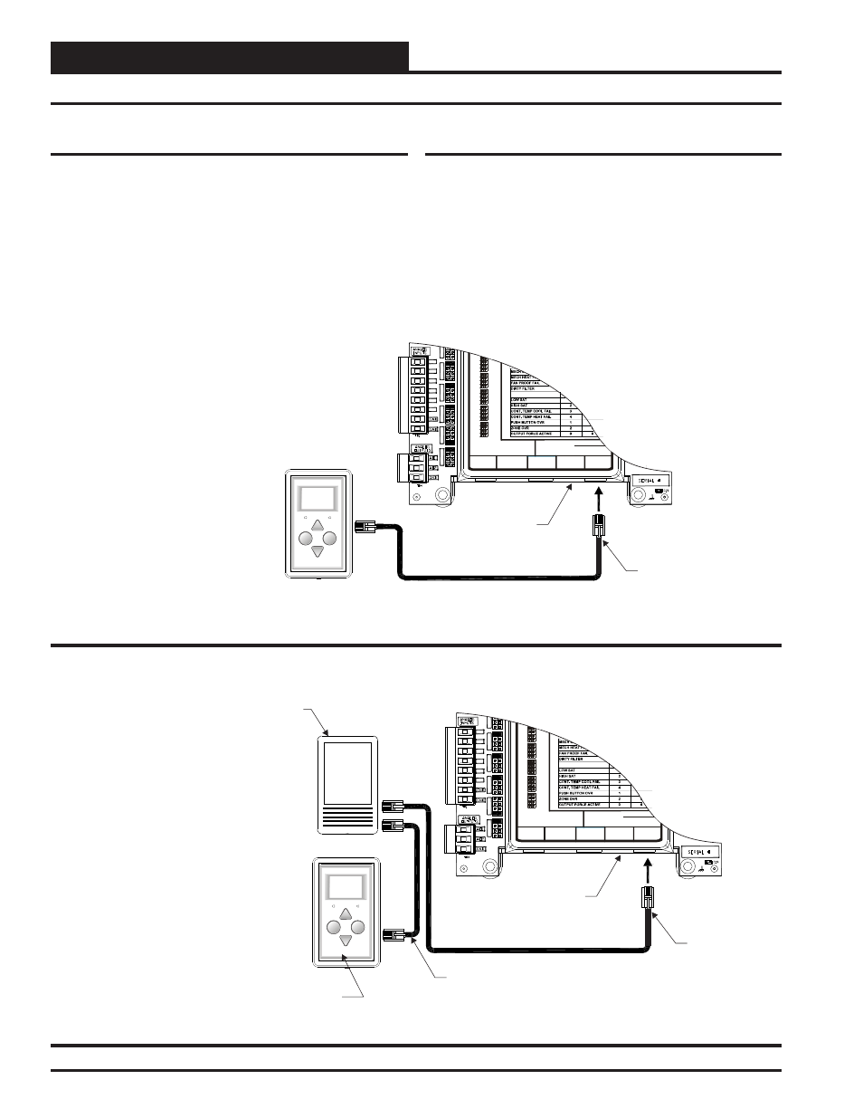
The OE217-00 Digital Room Sensor is used to sense Space Temperature
and the OE217-01 Digital Room Sensor is used to sense Space Tempera-
ture and Space Humidity. The Sensor connects to the VCM-X E-BUS
Controller with the TSDRSC modular cable. It can be daisy-chained
with the OE256-01 CO
2
Sensor for applications requiring both a room
CO
2
sensor and room temperature sensor. It should be mounted at ap-
proximately 5 Ft. above the fl oor on the wall in an area that does not have
drafts or is exposed to direct sunlight. See Figure 6 for wiring details.
I2C DIGITAL
SENSOR
I2C
EXPANSION
STATIC
PRESSURE
ANALOG INPUT JUMPER SETTINGS
MUST BE SET AS SHOWN FOR
PROPER OPERATION
24 VAC POWER ONLY
WARNING! POLARITY MUST BE OBSERVED
OR THE CONTROLLER WILL BE DAMAGED
AI2
AI3
AI4
THERM
THERM
THERM
THERM
4-20mA
4-20mA
4-20mA
4-20mA
4-20mA
0-10V
0-10V
0-10V
0-10V
0-10V
0-5V
0-5V
0-5V
0-5V
0-5V
AI5
AI7
WattMaster Label
#LB102033-01
AI1
I1
SET
AI2 SET
AI3 SET
AI4 SET
AI5 SET
AI7 SET
AI2
AI3
AI4
AI5
AI7
Digital Room Sensor
CO Sensor
2
TSDRSC Cable
TSDRSC Cable
Display
Override
OVERRIDE
ALARM
Note: When a Digital Room Sensor Is
Used In Combination With The
The
r Always
Connects To The VCM-X E-BUS
Controller First Using a TSDRSC Cable
Of The
Length. The Digital
Room Sensor Then Connects To The CO
Sensor With Another TSDRSC Cable.
CO
Sensor,
CO Senso
Required
Mount Sensor(s) At Least 5 Feet Above
Floor. See The
For Further Wiring
2
2
2
E-BUS C
Sensor
Technical Guide
O
2
EMERGENCY SHUTDOWN
VCM-X E-BUS
Controller
I2C DIGITAL
SENSOR
I2C
EXPANSION
STATIC
PRESSURE
ANALOG INPUT JUMPER SETTINGS
MUST BE SET AS SHOWN FOR
PROPER OPERATION
24 VAC POWER ONLY
WARNING! POLARITY MUST BE OBSERVED
OR THE CONTROLLER WILL BE DAMAGED
AI2
AI3
AI4
THERM
THERM
THERM
THERM
4-20mA
4-20mA
4-20mA
4-20mA
4-20mA
0-10V
0-10V
0-10V
0-10V
0-10V
0-5V
0-5V
0-5V
0-5V
0-5V
AI5
AI7
WattMaster Label
#LB102033-01
AI1
I1
SET
AI2 SET
AI3 SET
AI4 SET
AI5 SET
AI7 SET
AI2
AI3
AI4
AI5
AI7
VCM-X E-BUS
Controller
Digital Room Sensor
Display
Override
OVERRIDE
ALARM
TSDRSC Cable
Note: When Only The
Connects Directly To The VCM-X E-
BUS Controller Using A
Of The
Appropriate Length.
Digital Room Sensor
Is Used, It
TSDRSC Cable
The Maximum Length Allowed
Is 160 Feet. See For Connection When
The Space CO Sensor Is Also Used.
Figure 7
2
EMERGENCY SHUTDOWN
Figure 6: OE217-00/01 – Digital Room Sensor Wiring
Figure 7: OE256-01 – Wall Mounted Space CO
2
Sensor Wiring
Wall Mounted Space CO
2
Sensor
The OE256-01 Wall Mounted Space CO
2
Sensor is used to monitor CO
2
levels in the space served by the HVAC unit. The CO
2
Sensor connects to
the VCM-X E-BUS Controller with the TSDRSC modular cable. It can
be daisy-chained with the Digital Room Sensor ( OE217) for applications
requiring both a room CO
2
sensor and room temperature sensor. It should
be mounted at approximately 5 Ft. above the fl oor on the wall in an area
that does not have drafts or is exposed to direct sunlight. See Figure 7
for wiring details and installation notes. A Duct Mounted
CO
2
Sensor
can be used if desired instead of the Wall Mounted Space CO
2
Sensor.
See Figure 8 for Duct Mounted CO
2
Sensor wiring details.