Additional applications, Aaon, Wshp-x2 module overview and wiring – Orion System VCM-X Modular E-BUS User Manual
Page 46: Vcm-x modular e-bus controller technical guide 46
ADDITIONAL APPLICATIONS
VCM-X Modular E-BUS Controller Technical Guide
46
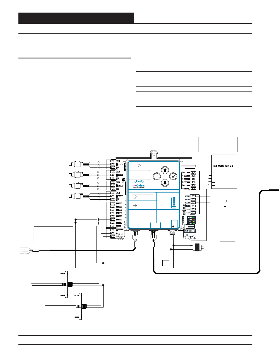
Figure 40: WSHP-X2 Module Dual Water Circuit Wiring Diagram
AAON
®
WSHP-X2 Module Overview and Wiring
AAON
®
Water Source Heat Pump X2
Module Dual Water Circuit
The OE334-26-WSHP-X2 Water Source Heat Pump X2 (WSHP-X2)
Module monitors the compressors on an AAON
®
Water Source Heat
Pump unit and can disable the compressors based on low Suction Pres-
sure, Leaving Water Temperature, and Water Proof of Flow inputs. It
also utilizes a Delay Timer to prevent the compressors from turning
on at the same time.
The WSHP-X2 Module’s water circuit confi guration can be either
single or dual. There are eight R410-A glycol confi gurations for the
WSHP-X2 Module—0%-40% in increments of 5%. There are two
refrigerant selections—R410-A refrigerant and R-22 refrigerant. If
R-22 refrigerant is selected, the glycol will automatically default to 0%.
The WSHP-X2 Module connects to the VCM-X WSHP E-BUS Con-
troller ( OE332-23E-VCMX-WSHP-A). This allows the Water Source
Heat Pump Module to receive control data and alarms from the VCM-X
WSHP E-BUS Controller. See Figure 40 below for a Dual water circuit
wiring diagram.
NOTE: The WSHP-X2 Module is factory set for R410-A and
0% glycol.
NOTE: For complete information, including the sequence of
operation, refer to the WSHP-X2 Module Technical Guide.
Connect To Other
WattMaster-Approved
E-BUS Expansion Module(s)
WARNING!! Observe Polarity! All
boards must be wired with GND-to-
GND and 24 VAC-to-24 VAC.
Failure to observe polarity could
result in damage to the boards.
HSSC Cable
Connect To VCM-X E-BUS
Controller or SA E-BUS Controller
WATTMASTER CONTROLS
Y 102374 REV 0
S
MADE IN USA
OE334-26-WSHP-X2
Water Source
Heat Pump X2 Module
NOTE:
NORMALLY OPEN AND
RATED FOR 24 VAC POWER
ONLY
ALL RELAY OUTPUTS
ARE
COMP. A2 ENABLE
COMP. A1 ENABLE
R1
R4
R5
R3
R2
COMM
COMP. B1 ENABLE
COMP. B2 ENABLE
ALARM OUTPUT
HVAC UNIT
CONNECTIONS
24 VAC Transformer
3 VA Minimum
Line Voltage
24 V
A
C
GND
WARNING!!
Observe Polarity! All
boards must be wired
with GND-to-GND and 24
VAC-to-24 VAC. Failure
to observe polarity could
result in damage to the
boards.
HSSC Cable
GND
T1
WATER POF A
BIN6
COM
E
LEAVING WATER TEMPERATURE
FOR SYSTEM B
LEAVING WATER TEMPERATURE
FOR SYSTEM A
T2
BIN7
WATER POF B
SIG 2
GND
+V
BK
RD
WH
SIG 1
GND
+V
BK
RD
WH
CIRCUIT A1
SUCTION PRESSURE
TRANSDUCER
SIG 2
GND
+V
BK
RD
WH
SIG 1
GND
+V
BK
RD
WH
CIRCUIT A2
SUCTION PRESSURE
TRANSDUCER
CIRCUIT B1
SUCTION PRESSURE
TRANSDUCER
CIRCUIT B2
SUCTION PRESSURE
TRANSDUCER
AOUT1
AOUT2
AOUT3
AOUT4
COMP A1
COMP A2
COMP B1
COMP B2
SEE
NOTE
BELOW
NOTE:
DIGITAL COMPRESSORS = 1.5-5 VDC
VFD COMPRESSORS = 0-10 VDC
WARNING!!
Observe Polarity! All
boards must be wired
with GND-to-GND and 24
VAC-to-24 VAC. Failure
to observe polarity could
result in damage to the
boards.
WattMaster Label
#S
000063
Rev.: 1B
W
E-BUS
HSSC
CONNECT
M
ENTER
UP
DOWN
ALARM
MENU
OE334-26-WSHP-X2 WSHP-X2 MODULE
AAON NO.: V48820
+24 V
A
C
GND
www.orioncontrols.com
www.aaon.com
- COMP A1 EN
- HEAT ENABLE
- COMP A2 EN
- H2O POF A
- COMP B1 EN
- H2O POF B
- COMP B2 EN
- COMMON
GND
- LEAVING WATER TEMP
- GROUND
- LEAVING WATER TEMP
AOUT1
- COMP A1
DIGITAL/VFD COMPRESSORS
A1, A2, B1, B2
RELAY CONTACT RATING
IS 1 AMP MAX @ 24 VAC
COMP. A2 ENABLE
COMP. A1 ENABLE
R1
R2
R3
R4
R5
RC
RELAY COMMON
COMP. B1 ENABLE
COMP. B2 ENABLE
ALARM OUTPUT
CONNECT TO
CNTLR C2
TERM.
+5V
PRES
GND
+5V
PRES
GND
SUCT. PR. SENSOR
PRES 1=A1, PRES 2=A2
PRES 3=B1, PRES 4=B2
NOT USED
PRES 1=A1, PRES 2=A2
PRES 3=B1, PRES 4=B2
+5 NOT USED, PRES TO P6 & GND TO P5
+5 TO RED, PRES TO WHT & GND TO BLK
DIGITAL COMRESSORS
NON-DIGITAL COMPRESSORS
AOUT2
- COMP A2
AOUT3
- COMP B1
AOUT4
- COMP B2
E-BUS
HSSC
CONNECT
BIN1
BIN2
BIN3
BIN4
BIN5
BIN6
BIN7
COM
T 1
T 2