Inputs & outputs, Expansion modules inputs & outputs, Vcm-x modular e-bus controller technical guide 52 – Orion System VCM-X Modular E-BUS User Manual
Page 52: 4 binary input expansion module, Relay expansion module, Zone
Zone
Zone
INPUTS & OUTPUTS
VCM-X Modular E-BUS Controller Technical Guide
52
*BI1 - Emergency Shutdown Input*
This wet contact input is used to initiate shutdown of the HVAC unit
when an N.C. Smoke Detector (by others), Firestat (by others), or other
shutdown condition (by others) contact is opened. The controller remains
active and can initiate alarm relays.
*BI2 - Dirty Filter Contact Closure Input*
This wet contact input is required for Filter Status Indication and requires
a Differential Pressure Switch to initiate “Dirty Filter” indication.
*BI3 - Proof of Flow Input
A Proof of Flow Switch that provides a wet contact closure whenever
the HVAC unit Supply Fan is operating can be connected to this input.
If the Proof of Flow Switch contact opens while the Supply Fan is op-
erating, all Heating and Cooling is suspended or disabled. The Proof of
Flow Switch is an optional input. This means that you must confi gure
the VCM-X E-BUS Controller to recognize this input signal.
*BI4 - Remote Forced Occupied Mode Input*
When this wet contact input closes, it will force the VCM-X E-BUS
Controller into the Occupied Mode. When the Remote Forced Occupied
Signal is removed, the controller will revert to the Unoccupied Mode
of operation if no internal or external schedule has been confi gured or
is in effect when this occurs.
BI5 - Remote Forced Heating Mode Input
This wet contact input is used to provide a means for another BAS or
control device (by others) to force the unit into Heating Mode when it
closes. See the note regarding Remote Force Mode Setting that follows.
BI6 - Remote Forced Cooling Mode Input
This wet contact input is used to provide a means for another BAS or
control device (by others) to force the unit into Cooling Mode when it
closes. See the note regarding Remote Force Mode Setting that follows.
NOTE: Remote Forced Heating or Cooling Modes require that you
enter a value of 1 for both the Heating and the Cooling Setpoints for the
HVAC Mode Enable and the Mode Enable Sensor must be set as Supply
Air Temperature. The VCM-X E-BUS Controller will then look for wet
contact closures on the Remote Forced Cooling Mode and Remote Forced
Heating Mode inputs to enable the HVAC Modes. If both the Remote
Forced Heating and Remote Forced Cooling Modes are active, the unit
will operate in Vent Mode. The unit may also be operated in Vent Mode
by providing a wet contact closure signal to the Remote Occupied Input.
BI7 - Exhaust Hood On Input
When this wet contact input closes, the VCM-X E-BUS Controller
switches from Indoor Air Control to Outdoor Air Control. This is typically
used on CAV applications requiring MUA/CAV Dual Damper (Hood
On/Off) Modes.
BI8 - Remote Forced Dehumidifi cation
This wet contact input is used to provide a means for another BAS or con-
trol device (by others) to force the VCM-X E-BUS Controller into Dehu-
midifi cation Mode. You must set the Dehumidifi cation Spt Indoor RH to
100% for the Remote Forced Dehumidifi cation feature to function.
* 4 Binary Input Expansion Module
A 4 Binary Input Module can be used in lieu of using the VCM-X Ex-
pansion Module when only the fi rst 4 Binary Inputs are required. You
can use the VCM-X Expansion Module or the 4 Binary Input Expansion
Module, but not both.
12-Relay Expansion Module
Please refer to the user-confi gurable relays in Table 2, below, for relay
defi nitions.
Expansion Modules Inputs & Outputs
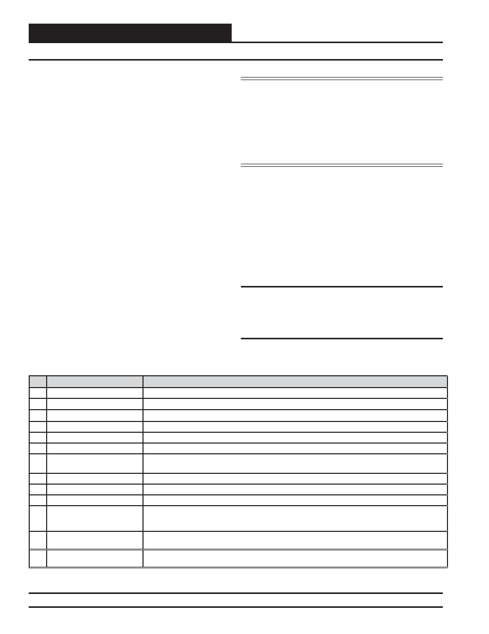
Table 2: User-Confi gurable Relay Outputs
No.
Relay Description
Details
1
Heating Stages
Confi gure (1) Relay for each stage of heat. Confi gure (1) Relay for Mod heat.
2
Cooling Stages
Confi gure (1) Relay for each stage of cooling. For chilled water, confi gure (1) Relay for cooling.
3
Warm-Up Mode (VAV Boxes)
Confi gure (1) Relay for Warm-Up Mode when Non-Orion VAV/Zone Controllers are used.
4
Reversing Valve (Heat Pumps)
Confi gure (1) Relay for Reversing Valve operation. Can be confi gured for heating or cooling.
5
Reheat
Confi gure (1) Relay for On/Off reheat when used.
6
Exhaust Fan
Confi gure (1) Relay for enabling exhaust fan when building pressure control is used.
7
Pre-Heater
(Low Ambient Protection)
Confi gure (1) Relay for pre-heat coil when required. Activated when the outdoor air temperature drops
below the ambient protection setpoint.
8
Alarm
Confi gure (1) Relay to initiate an alarm output when any VCM-X alarm occurs.
9
Override
Confi gure (1) Relay to initiate an output signal when space temperature override button is pushed.
10
Occupied Confi gure (1) Relay to initiate an output signal any time the VCM-X is in occupied mode.
11
OA Damper
Confi gure (1) Relay to initiate an output signal when the OA damper moves beyond its minimum during
economizer operation, or when the OA damper opens in a MUA application, or when the damper opens
during Hood On operation.
12
Heat Wheel
Confi gure (1) Relay that turns heat wheel on when in occupied operation and turns heat wheel off when
in economizer mode.
13
Emergency Heat
Confi gure (1) Relay for fi xed stage Emergency Heat in a heat pump unit. Not available on VCM-X WSHP
E-BUS controller.