Thinklogical X4 Configurator Manual User Manual
Page 23
X4 Configurator Manual
23
October, 2012
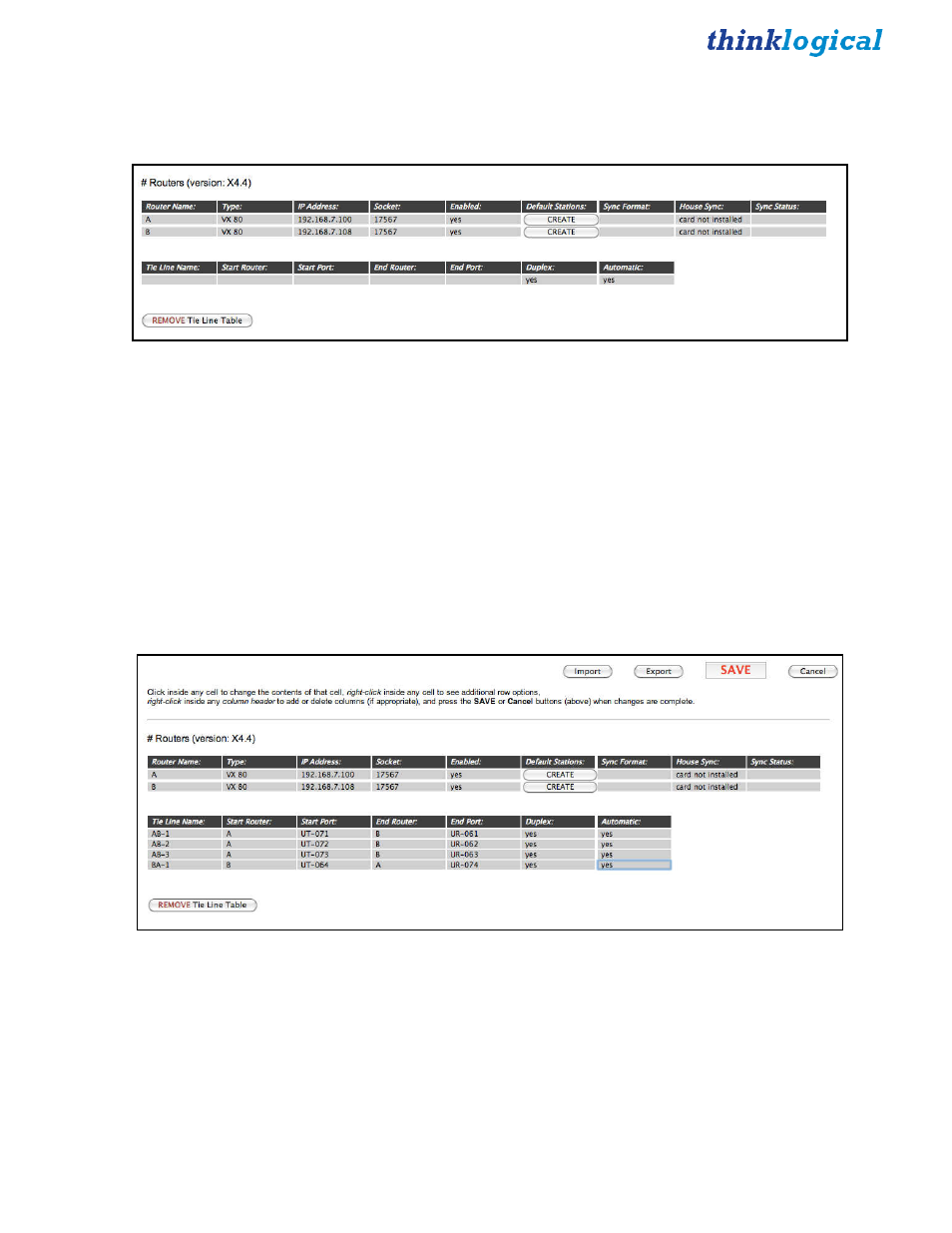
Next, create the Tie Line Table. This is done by clicking the “ADD Tie Line Table” button on the bottom
left. When clicked, it will insert a headers and a single, blank row for the first tie line (and replaces the
Add Tie Line Table button with a REMOVE Tie Line Table button).
Add the values for the first tie line. The start port is where the signal will exit the start router and will be a
Transmit. The end port is where the signal enters the end router and will be a Receive port. Duplex means
there is a second fiber for the return channel, so since duplex is true in this case, it would be on router A
at port UR-071 and router B at UT-061.
The easiest way to add new tie lines is to:
1.
Right click on the first one and select Copy.
2.
Right click on the first one again, select Append.
3.
Right click on the new, blank line and select Paste.
The choice of each tie line name is up to the administrator. It is used to uniquely identify the tie line to the
program and for diagnostics as we will see later. Make sure that the Duplex and Automatic columns are
set to “yes”.
In this case, we have created three duplex paths from A to B and one from B to A. Click
SAVE
when
done
.
Next, we need to create stations on both routers. If you are using one of the default files created
automatically by X4, it probably has many more stations than are needed. Use the ADMIN Stations
Export function to save a copy of stations.csv, and edit it using a spreadsheet program like Excel or Open
Office.