Nms connection -12, Nms in/out -12 – Verilink 2000 (34-00182) Product Manual User Manual
Page 24
2-12
I
NSTALLATION
The supervisory port bit rate must be set as
described in Supervisory Port Bit Rate on page
2-7 (Switch S4-5 and S4-6). The physical
connection is a 6- pin modular connector with the
pinout shown in Table 2-10. This is a serial RS-232
DCE port configured for 8 bits, no parity, and 1
stop bit.
NMS
Connection
The 2000 CSU is fully compatible with the TxPORT EM8000 Element Manager
and the 8100A Site Controller. The EM8000 software system and the 8100A Site
Controller are used to manage small to large networks of TxPORT network access
products. The different connection methods are described in the following
paragraphs.
NMS IN/OUT
The two 6-pin modular connectors labeled NMS IN and NMS OUT on the rear
panel may be used for connection to the EM8000 or 8100A. This port is
configured in this manner to allow the connection of multiple collocated units in a
daisy chain IN /OUT bus arrangement as shown in Figure 2-7.
The OUT port of one element is connected to the IN port of the next element, and
so on, to form a complete chain among the group of elements.
Table 2-10 SUPV Port Interface Pinout
Pin
SUPV Port Interface
1
Not Used
2
Signal Ground
3
Data Out
4
Data In
5
Signal Ground
6
Not Used
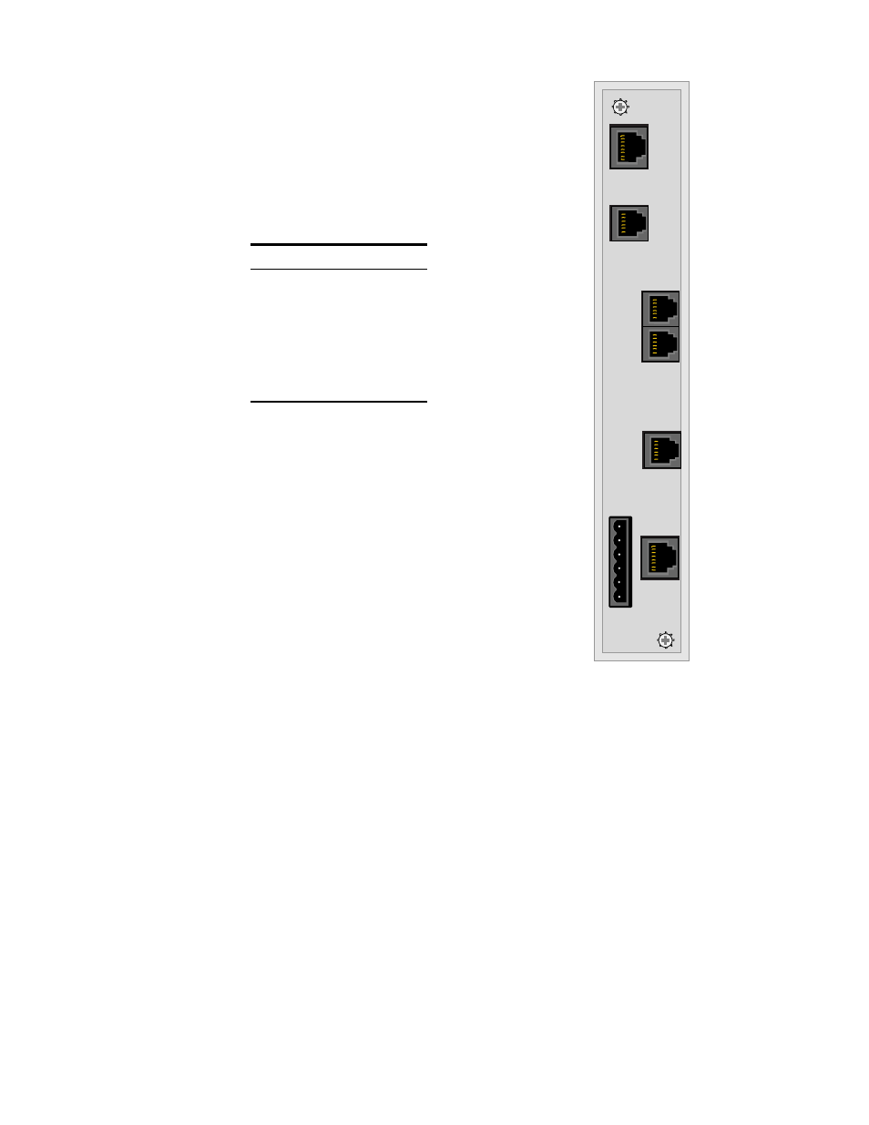
Figure 2-6 2000 Rear Panel
DB-15
(optional)
DB-15
(optional)
8
1
1
6
1
6
1
6
1
6
1
1
6
8
Power/
Alarm
NMS
IN/OUT
NMS
OUT
Network
Interface
SUPV
DTE
Interface
External
Clock
(not used)