Nms in only -13 nms split cable -13 – Verilink 2000 (34-00182) Product Manual User Manual
Page 25
Network Management
2-13
All units on the same NMS chain must use the same NMS bit rate whether in a chassis or
stand-alone housing.
NMS IN Only
The NMS IN connector provides both the transmit and receive signal pair. This
port may be used for a modem connection or as a VT100 terminal interface
(explained in the Terminal Operation chapter).
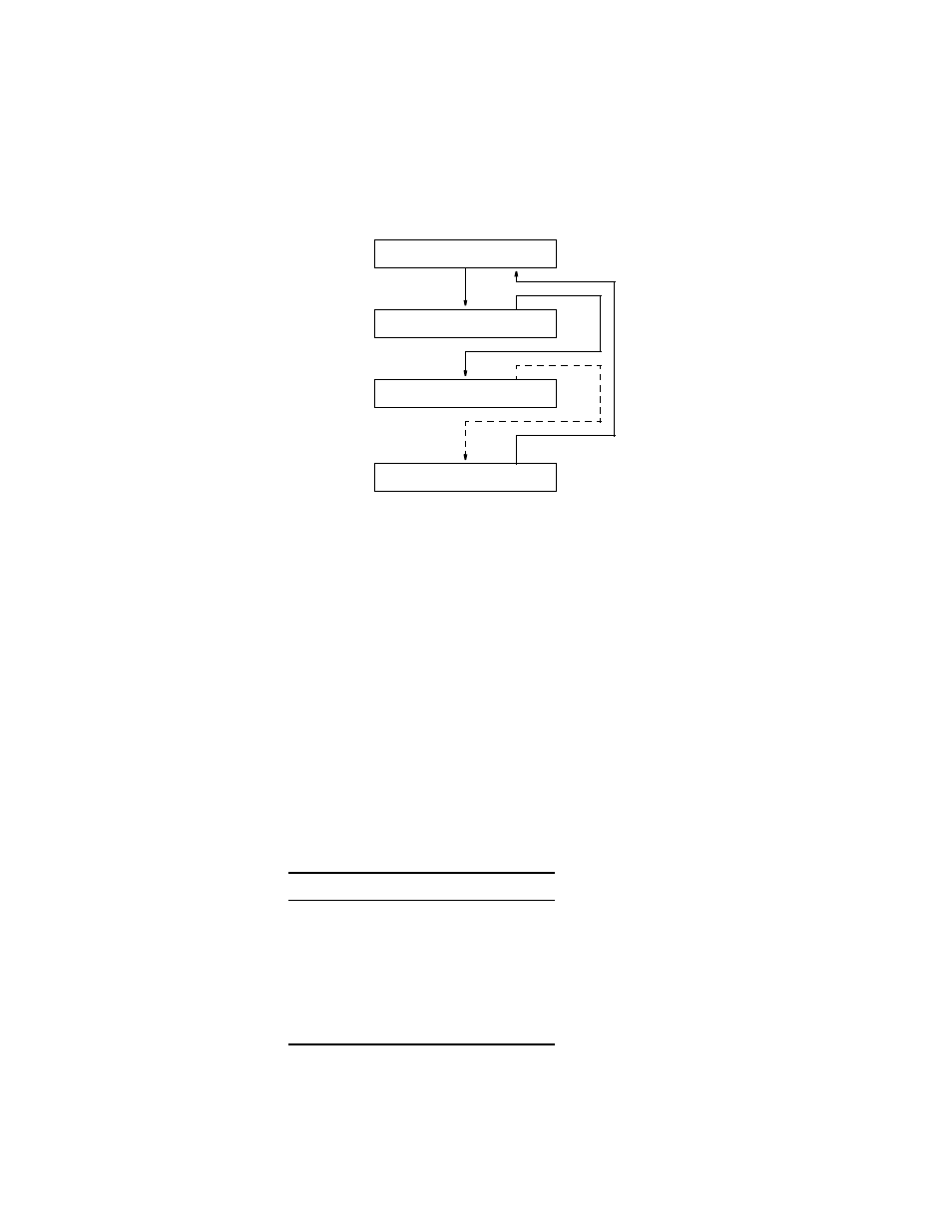
NMS Split Cable
The EM8000 or 8100A may be connected directly into the NMS chain between
two elements. The EM8000 may also be connected to the SUPV port if the NMS
connection is not desirable. A Y cable is used from the EM8000 serial port which
splits the transmit and receive signals into two 6 -pin modular connectors for the
NMS IN and NMS OUT ports. Ordering information for this cable is found in
Optional Equipment on page 1-7.
The NMS address, port bit rate, and power up configuration mode may be set by
either the configuration switches or through software control. The NMS bus
physical connection is a 6-pin modular connector with the following pinout shown
in Table 2-11. This port is a serial RS-232 DCE port configured for 8 bits, no
parity, and 1 stop bit.
Table 2-11 NMS Bus Pinouts
Pin
NMS Bus IN
NMS Bus OUT
1
Not Used
Not Used
2
Signal Ground
Signal Ground
3
Data Out
Data Out
4
Data In
Not Used
5
Signal Ground
Signal Ground
6
Not Used
Not Used
IN
OUT
NMS
IN
OUT
NMS
Element
Element
OUT IN/OUT
NMS
EM8000
or 8100A
IN
OUT
NMS
Last
Element
Figure 2-7 NMS Daisy-Chain Arrangement