Connector interface modules, T1 cim, E1 cims – Verilink DCSU 2911 (880-502647-001) Product Manual User Manual
Page 11: Connector interface modules -3, T1 cim -3 e1 cims -3, One t1 ds-1/dsx-1 i/o cim is available
DCSU 2911 Dual Channel Service Unit
Verilink DCSU 2911 User Manual
1-3
Connector Interface Modules
Rear connector modules or connecter interface modules (CIMs)
provide connections to the network and various types of customer-
provided equipment (CPE).
They also provide the following connections:
•
Alarm relay
These contacts can be wired to an external alarm equipment.
The connector pins provide output as a normally open (NO)
contact, a normally closed (NC) contact, and a common (COM)
lead contact.
Loss of carrier conditions activate the relay contacts. For more
information on alarms, see Chapter 4, Troubleshooting.
•
External timing source input
The 8-pin mini-DIN connector receives clock from an external
timing device.
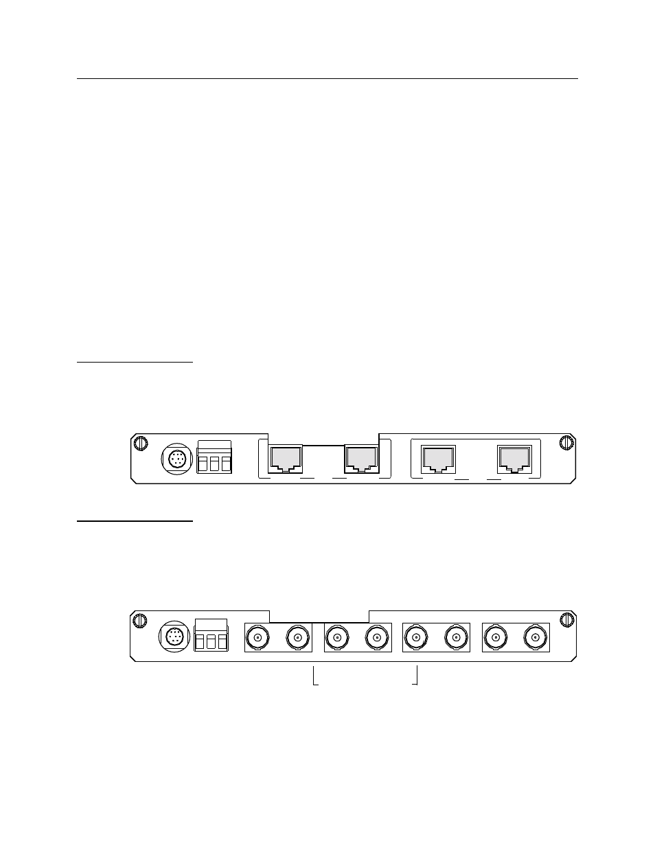
T1 CIM
One T1 DS-1/DSX-1 I/O CIM is available:
•
CIM 29003 DS-1/DSX-1 RJ-45 (100
Ω
) (Fig. 1-3)
Figure 1-3 CIM 29003 DS-1/DSX-1 RJ-45 (100
Ω
)
E1 CIMs
Two E1 Connector Interface Modules (CIMs) are available:
•
E1 CIM 29001 LP BNC (75
Ω
) (Fig. 1-4)
•
E1 CIM 29002 LP RJ-45 (120
Ω
) (Fig. 1-5)
Figure 1-4 CIM 29001
LP
BNC E1 (75
Ω
)
ALARM
RELAY
NO COM NC
311-
XXXX
X
-1
00
INPUT
EXT TIMING
PORT4
PORT3
PORT 2
PORT 1
CI
M
290
03
DSX-1
DS-1
3
1
1
-X
XXXX
-3
0
1
RELAY
NO COM NC
CEPT E1
RX
TX
RX
TX
NET 2
NET 1
ALARM
CIM
2
900
1 L
P
RX
TX
RX
TX
CPE 2
CPE 1
INPUT
EXT TIMING
BNC female connectors
Cutout