Interpreting front panel leds, Network port leds, Interpreting front panel leds -6 – Verilink DCSU 2911 (880-502647-001) Product Manual User Manual
Page 72: Network port leds -6
Troubleshooting
5-6
Verilink DCSU 2911 User Manual
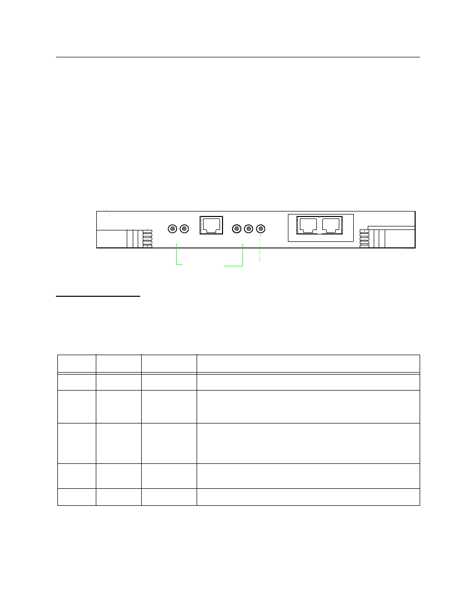
Interpreting Front Panel LEDs
The LED indicators on the front panel of the DCSU 2911 module
display errors caused by T1 line or data terminal equipment
problems. The errors are reflected in the alarm status and the
performance/status menus in the Craft interface. Node Manager
also has an alarm display.
There are five LEDs on the front panel:
•
Two T1 port LEDs
•
Two data port LEDs
•
One system LED
Figure 5-2 DCSU Front Panel
Network Port
LEDs
The network port LEDs display minor, major, and critical alarm
conditions detected on the network line. Net LED 1 and Net LED 2
display alarm status for their respective network ports. Table 4-1
provides a brief description of the network port LED states:
Table 5-2
Network LED Indicators
MANAGEMENT
SYS
LOCAL
2
NET
DATA
1
2
1
DC SU
Port LEDs
System LED
PRI
EXT
2911
State
Color
Alarm Class
Action/Possible Error Condition
Solid
Green
All okay
None
Solid
Amber
Diagnostic
mode with no
errors
None
Flashing
Amber
and Red
Yellow Alarm
Check the diagnostic performance status or alarm status
displays. The Yellow Alarm indicates that the unit is receiving
an RAI Signal, which indicates that the far end is not receiving a
signal from the near end.
Solid
Red
Major
Check the performance status or alarm status display. Loss of
Signal (LOS) from far end transmits all-ones.
Off
None
None
Port is not enabled.