Overview of fbr and brc hardware, Overview of the rems component connections, Overview of fbr and brc hardware -5 – Verilink Red Zone Encryption (REMS) (880-502423-001) Product Manual User Manual
Page 25: Overview of the rems component connections -5
Overview of FBR and BRC Hardware
Red Zone Encryption Management System (REMS) User Manual
2-5
Overview of FBR and BRC Hardware
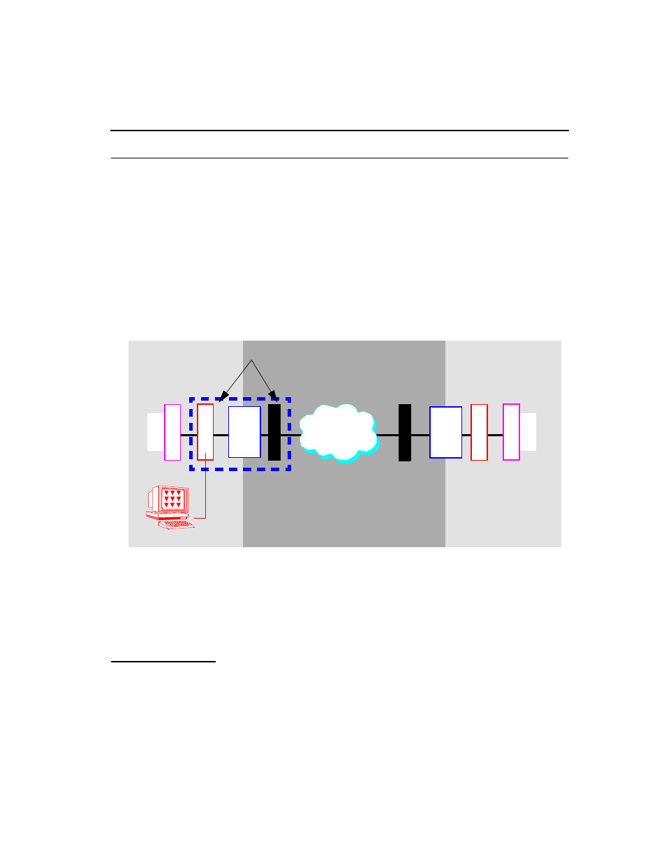
The Red Zone Encryption Management System consists of two major
components: Frame Bit Repositioner (FBR) and Black to Red
Communicator (BRC). The FBR is installed on the Red Zone side and
communicates between the DTE equipment and the encryptor. The FBR
also connects to the PC running Access Manager. The BRC is installed on
the Black Zone side of the encryptor and communicates with the network.
On the far-end, another REMS is also installed. See Fig ure2-5, Block
Diagram of REMS showing Functional Components.
Figure 2-5
Block Diagram of REMS showing Functional Components
The dashed lines on the left show the REMS broken into its two main
functional components, the FBR and the BRC. In addition to their
specific functions, both the Frame Bit Repositioner (FBR) and the
Black-to-Red Communicator (BRC) provide full CSU functionality,
including transcoding and performance data registers.
Overview of the
REMS component
connections
Both the FBR and the BRC are composed of front and back modules.
Back modules are called Rear Connector Modules. The front modules
contain the microprocessor-based engines that perform the essential
Red Zon
Common Carrier
or
Local Exchange
Networ
B
R
C
B
R
C
F
B
R
M
U
X
Black Zone
Red Zon
Access Manager 2000
M
U
X
F
B
R
KG81
Encryptor
KG94
KG81
Encryptor
KG94
Near-End
Far-End
REMS components go on both sides of the encryptor.