Fbr ncc 2020, Fbr ncc 2020 -4, Fbr and brc components of rems – Verilink Red Zone Encryption (REMS) (880-502423-001) Product Manual User Manual
Page 44: The front panel of the fbr ncc 2020 contains, A momentary push-button switch (labeled exe)
FBR and BRC components of REMS
4-4
Red Zone Encryption Management System (REMS) User Manual
■
Provides “Red Zone” alarm notification in the event that the register
count exceeds the preset threshold
■
Repositions the framing bit provided by the DTE to correspond with
the BRC inserted framing bit. This proprietary alignment technique
is the key to full bandwidth operation. (For more information, see
Chapter 3, Theory of operation.)
FBR NCC 2020
The FBR NCC 2020 connects to the MUX via its Rear Connector
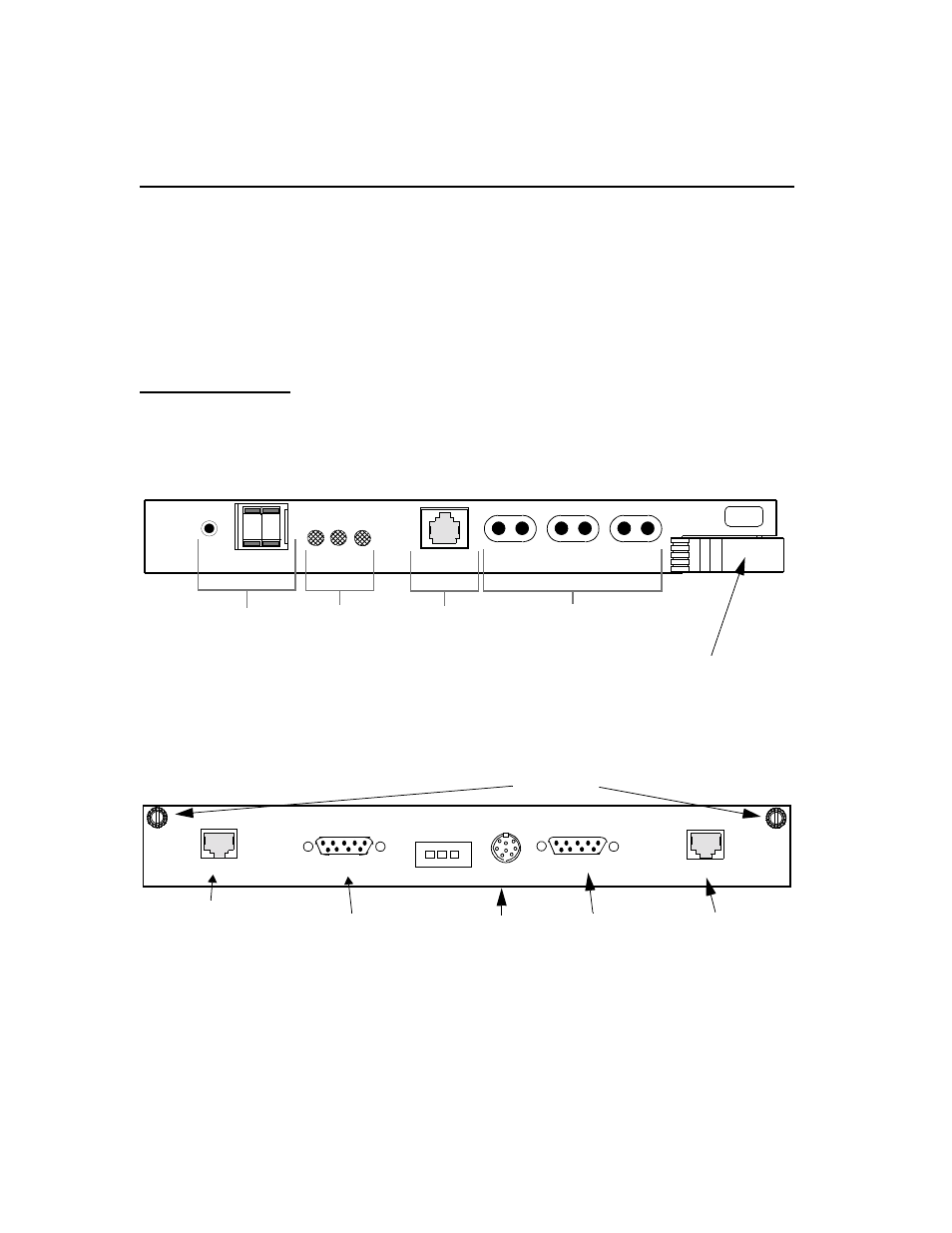
Module, the CIM 2020. Figure4- 3, NCC 2020 Front Panel shows the
NCC 2020 front panel controls and indicators.
Figure 4-3
NCC 2020 Front Panel
Figur e4-4, FBR CIM 2020 Rear Panel (Back Module for NCC 2020),
shows the rear connector panel of the NCC 2020’s mating back-module.
Figure 4-4
FBR CIM 2020 Rear Panel (Back Module for NCC 2020)
The front panel of the FBR NCC 2020 contains:
■
a momentary push-button switch (labeled EXE)
REV
MON
NET
NET
OUT
CRAFT
NE
T
ST
A
T
EQ
P
T
FUNCTION
EX
E
IN
NCC
0
0
2
020
Thumbwheel
Interface
LED
Indicators
ASCII
Interface
Signal Access
Jacks
EQPT
OUT
IN
EQPT
Thumbwheel Switches
and Command
Execution Push button
Equipment, CSU
Network LEDs
Status, and
Modular Jack
Connection
ASCII Terminal
for
(Bantam)
Ejector handle
To MUX
NC
EXT
TIMING
CIM
20
25
NO COM
ALARM
RELAY
MANAGEMENT PORT IN
MANAGEMENT
Not used
EQPT
Not used
EXTENSION
NETWORK
This CIM mates with NCC 2020 front module.
To PC COM port
Not used
Thumb screws
ESF/D4 1.544 MHz in