Verilink Red Zone Encryption (REMS) (880-502423-001) Product Manual User Manual
Page 26
System Overview
2-6
Red Zone Encryption Management System (REMS) User Manual
functions of the modules. The back modules provided equipment and
network connectivity. Engine modules are based on standard AS2000
modules but contain modified Flash EPROMs and other electronics. Rear
Connector Modules are also based on standard AS2000 modules.
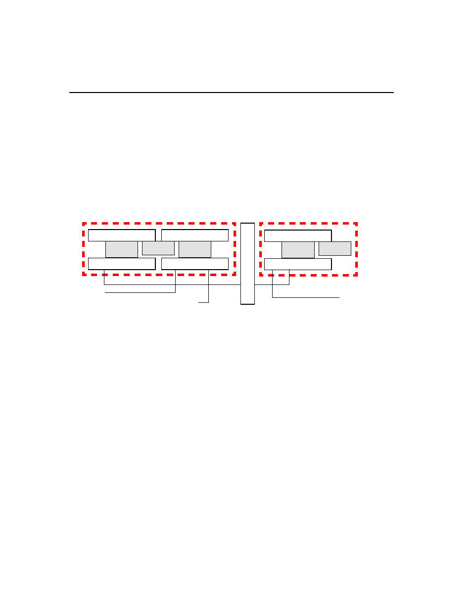
Figur e2-6, Functional Block Diagram of REMS Component Modules
and Encryptor shows the modular breakdown of the REMS components
and their interconnectivity with the equipment side, the encryptor, and the
network.
Figure 2-6
Functional Block Diagram of REMS Component Modules and Encryptor
For a further descriptive breakdown of the FBR and BRC, see Chapter 4,
FBR and BRC components of REMS
KG
-X
X E
n
c
ryp
to
r
128-pin
NCC 2020
connector
CDM 2049
Shelf
backplane
To network
BRC
FBR
128-pin
NCC 2020
connector
CIM 2020
128-pin
DIU 2130
connector
DIM 253
Shelf
backplane
MUX
To PC/Access Manage
Encryptor —>
D4/ESF