Setting the shelf address switch, Setting the shelf address switch -7, Using shelf rear panel functions – Verilink Red Zone Encryption (REMS) (880-502423-001) Product Manual User Manual
Page 89
Using shelf rear panel functions
Red Zone Encryption Management System (REMS) User Manual
9-7
If more than one shelf is installed, all system shelves must be within 12
cabling feet (3.657 m) of each other.
Setting the shelf
address switch
The address switch (SW1), located on the back of a dual-line shelf, sets
the shelf identity within a node. The address switch on the first shelf in
your node should be set to 0. If you have two shelves in your node, the
address switch on the second shelf should be set to 1. (See the diagram
below:)
Figure 9-5
Dual-line Shelves and Slot Identification Diagram
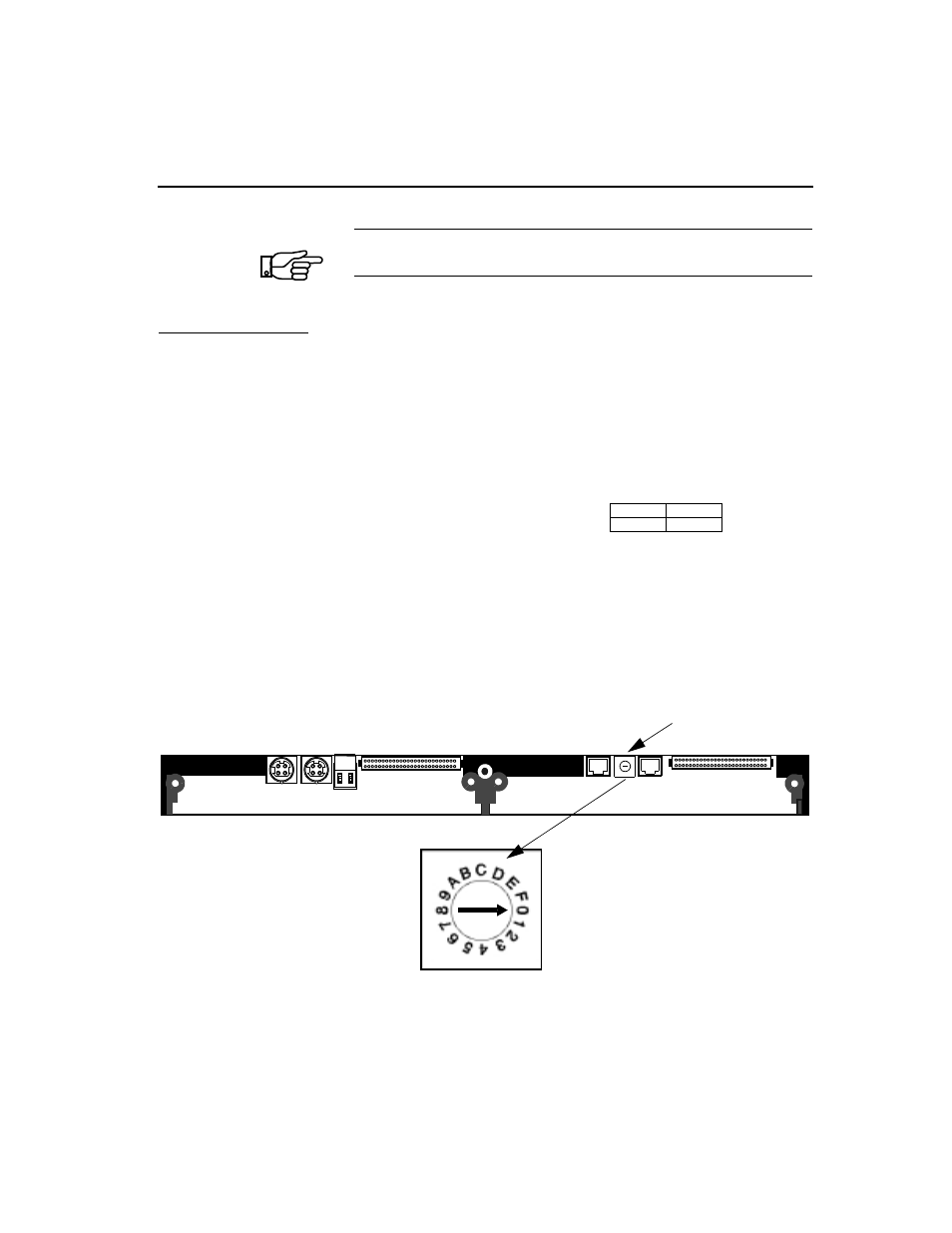
On a multiline shelf, the shelf address switch is located on the power
supply circuit board and is also labeled SW1. The circuit board is
accessible from the rear of the shelf. See Figure9-6, Rear Panel View of
Dual-line Shelf Showing Shelf Address Switch.
Figure 9-6
Rear Panel View of Dual-line Shelf Showing Shelf Address Switch
NOTE
NCC Module is always on the left.
Front view schematic of double dual-line shelf
Shelf 0
Shelf 1
NCC
-
Slot 1
Slot 2
-
-
C
B
A
9
8
7 6
5
4
3
2
1
0
FE
D
J3
J4
1 2
Shelf Address Switch (SW 1)