Verilink Red Zone Encryption (REMS) (880-502423-001) Product Manual User Manual
Page 92
Installing and Replacing Plug-in Modules
10-2
Red Zone Encryption Management System (REMS) User Manual
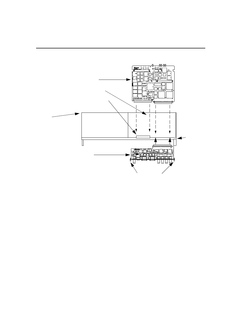
Figure 10-1 Front Module and Rear Connector Module Installation in a Dual-line Shelf, Top View
The 128-pin female connector J1 side of the rear connector module
should be facing to the interior of the shelf. Its rear connector panel
should be facing to the outside rear of the shelf.
4.
Insert the rear connector module into the slot 1 position of the dual-
line shelf so that the rear connector module seated with rear panel is
flush with the rear panel of the shelf. Make sure it is squarely
aligned. Seat it by gently pushing it all the way in until it stops and
you can hand start the thumbscrews.
5.
Secure the rear connector module by tightening the two thumbscrews
on the rear panel as shown in Figure 1 0 -2, Securing a Rear Connector
Module into a Dual-line Shelf Using the Thumbscrews.
Dual-line shelf
(Top View)
CIM Module
Front module
Dual-line shelf Front
Shelf
Slot 2 position
Mating backplane connecto
Shelf 0, slot1 position
Panel
Backplane
Thumbscrews
F
ront
module