Verilink Red Zone Encryption (REMS) (880-502423-001) Product Manual User Manual
Page 42
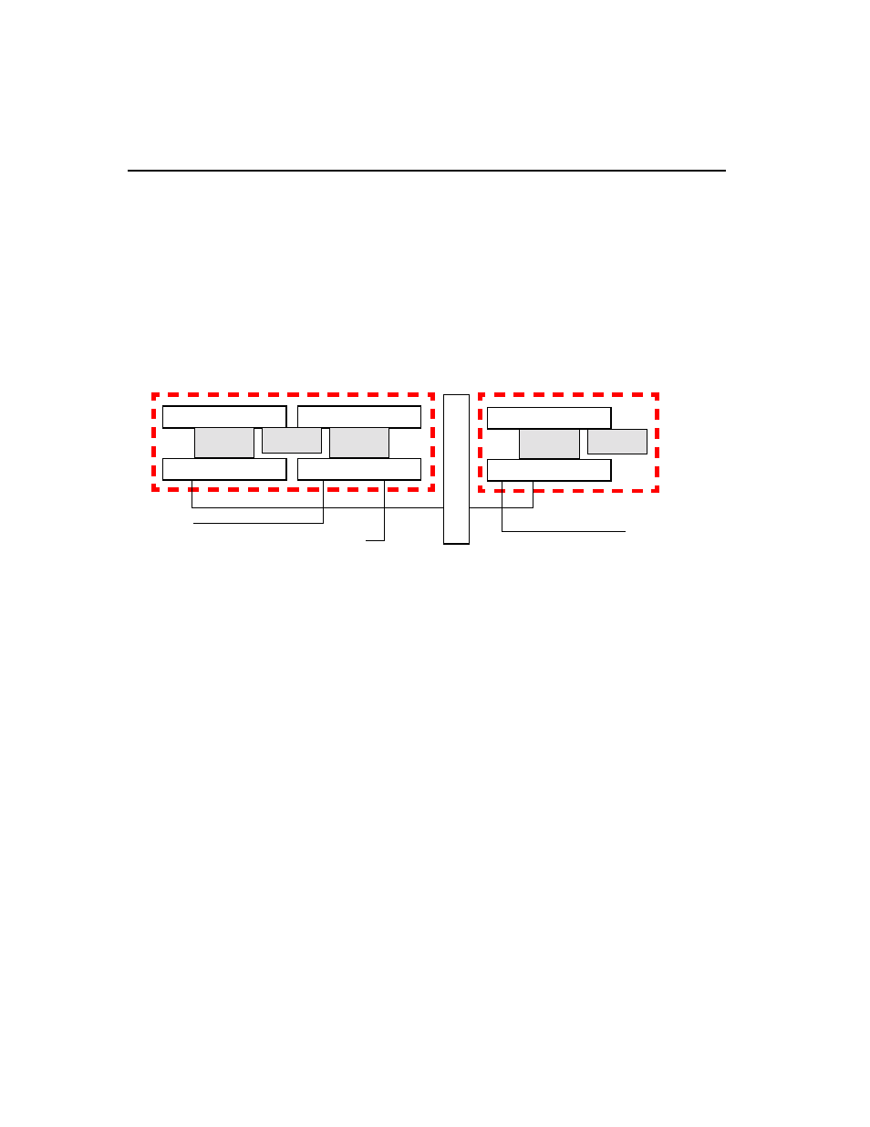
FBR and BRC components of REMS
4-2
Red Zone Encryption Management System (REMS) User Manual
network connectivity. Engine modules are based on standard AS2000
modules but contain modified Flash EPROMs and other electronics. Rear
Connector Modules are also based on standard AS2000 modules.
Figur e4-1, Functional Block Diagram of REMS Component Modules
and Encryptor shows the modular breakdown of the REMS FBR and
BRC and their interconnectivity with the multiplexers, the Encryptor, and
the network.
Figure 4-1
Functional Block Diagram of REMS Component Modules and Encryptor
KG
-X
X E
n
c
ryp
to
r
128-pin
NCC 2020
connector
CDM 2049
Shelf
backplane
To network
BRC
FBR
128-pin
NCC 2020
connector
CIM 2020
128-pin
DIU 2130
connector
DIM 253
Shelf
backplane
MUX D4/
To PC/Access Manage
Encryptor —>
ESF
- 1061 T1 Multicast (34-00268) Product Manual (18 pages)
- 2010 (34-00204) Product Manual (15 pages)
- 1558A (34-00228) Product Manual (39 pages)
- 1558D (34-00255) Product Manual (42 pages)
- 210 (34-00196) Product Manual (9 pages)
- 2000 (34-00182) Product Manual (58 pages)
- 300 (34-00199) Product Manual (9 pages)
- 2048 (34-00179) Product Manual (33 pages)
- 400 (34-00222) Product Manual (9 pages)
- 2100 (34-00187) Product Manual (19 pages)
- 7200p Series IAD (34-00334.B) Product Manual (311 pages)
- APS 2000 T1 Line Protection (880-502411-001) Product Manual (87 pages)
- AS200 (896-502379-001) Product Manual (112 pages)
- AS420 (34-00294) Product Manual (28 pages)
- AS56/56Plus (896-502588-001) Product Manual (130 pages)
- 9000 Series (34-00271) Product Manual (440 pages)
- AS2000: The Basics (880-502981-001) Product Manual (179 pages)
- Access Manager 2000 (896-502037-001) Product Manual (400 pages)
- ConnecT 56K DSU (896-502110-001) Product Manual (88 pages)
- AS4000 (34-00244) Product Manual (210 pages)
- C150 (880-502893-001) Product Manual (135 pages)
- Craft Interface (No Part Number) Product Manual (8 pages)
- DDS Lite (34-00295.C) Product Manual (19 pages)
- DCSU 2911 (880-502647-001) Product Manual (79 pages)
- DIDCSU 2912 (880-502646-001) Product Manual (107 pages)
- DIU 2130 (880-503297-001) Product Manual (101 pages)
- DIU 2131 (880-502765-001) Product Manual (31 pages)
- FrameStart FSE (34-00291.F) Product Manual (49 pages)
- DPRI 2922 (880-503142-001) Product Manual (91 pages)
- HDM 2180 (880-503048-001) Product Manual (79 pages)
- HDM 2182 (880-502925-001) Product Manual (81 pages)
- IMUX (880-503137-001) Product Manual (48 pages)
- FrameStart FSM (34-00299.E) Product Manual (153 pages)
- TAC 2010 (880-503298-001) Product Manual (65 pages)
- M1-3 (880-503136-001) Product Manual (75 pages)
- NCC 2130 (880-503285-001) Product Manual (61 pages)
- NCM 2000 (880-502623-001) Product Manual (91 pages)
- NetPath 2000 Product Manual (30 pages)
- PRISM 3000 (34-00184) Product Manual (45 pages)
- PRISM 3001 (34-00186) Product Manual (58 pages)
- PRISM 3002 (34-00277) Product Manual (52 pages)
- Net Engine (3150-30626-001) Product Manual (323 pages)
- PRISM 3021 (34-00262) Product Manual (47 pages)
- PRISM 3010 Dual DSX-1 (34-00250.2) Product Manual (22 pages)
- PRISM 3060-10 (34-00252.4) Product Manual (76 pages)