10 profibus data exchange – Watson-Marlow Qdos30 User Manual
Page 34
Watson-Marlow qdos30 PROFIBUS Pump User Manual
34
14.10 PROFIBUS data exchange
The data in this section is provided as reference material for a PROFIBUS network
operator. Operating this pump under PROFIBUS control is beyond the scope of this
instruction manual. Consult your PROFIBUS network literature for further information.
Default address: 126
PROFIBUS Ident: 0x0E7D
GSD File: WAMA0E7D.GSD
Config: 0x62, 0x5D (3 words out, 14 words in)
User Parameter bytes: 6
Cyclic Data Write (from Master to pump)
Cyclic Data Write (from Master to pump)
16 bit
Byte 1, 2
Control Word
16 bit
Byte 3, 4
Pumphead Speed Setpoint (unsigned)
16 bit
Byte 5, 6
Set Flow Calibration in μl per revolution
Control Word
Bit
Description
0
Motor running (1= Running)
1
Direction (0= CW, 1= CCW)
2
Tacho Reset (1= Reset Count)
3
Reserved
4
Enable Fieldbus Min/Max Speeds (1= Enabled)
5
Enable Fieldbus Flow Calibration (1= Enabled)
6
Ignore leak detection sensor
7
Fluid Level Reset
8-15
Reserved
Pumphead Speed Setpoint
The speed setpoint is a 16-bit unsigned integer value that represents the speed of
the pump head in 1/10th of RPM. For example 1205 represents 120.5 RPM.
Set Flow Calibration
This parameter is used to set the flow calibration value from the fieldbus interface.
The value is a 16 bit unsigned integer representing μl per revolution. Note that this
value is only used if bit 5 of the Control Word is enabled.
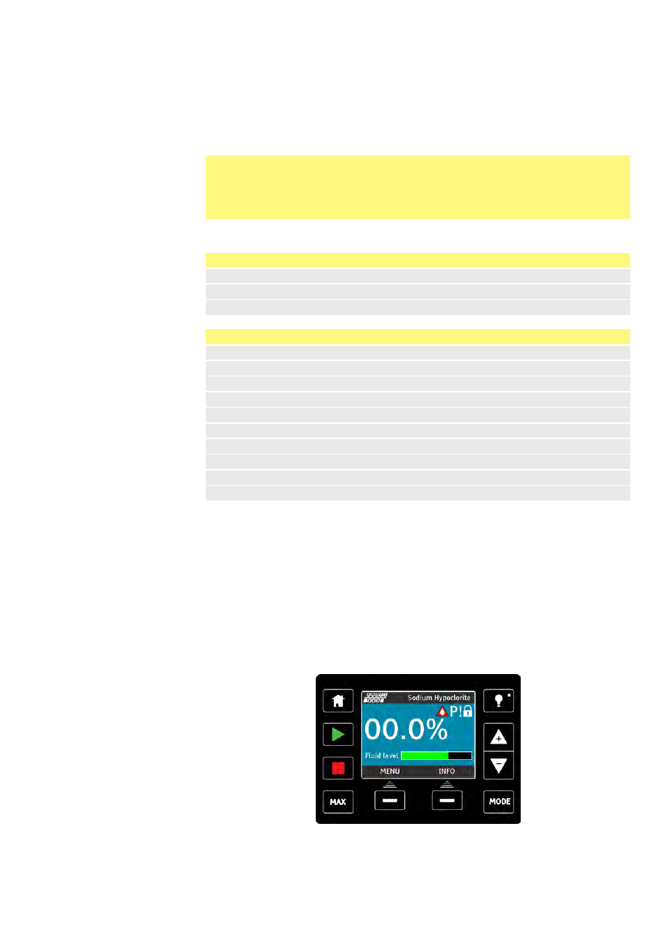
Ignore Leak Detection Sensor
If bit 6 of the control word is enabled, the following run screen will be displayed.