Watson-Marlow SPS User Manual
Page 88
MasoSine SPS sinusoidal pumps User Manual
88
22.4.2 Assembling the SPS 250, SPS 300,
SPS 400 and SPS 500
During assembly, check that all O-rings are properly positioned before fitting each
component, and that all components are clean and lubricated.
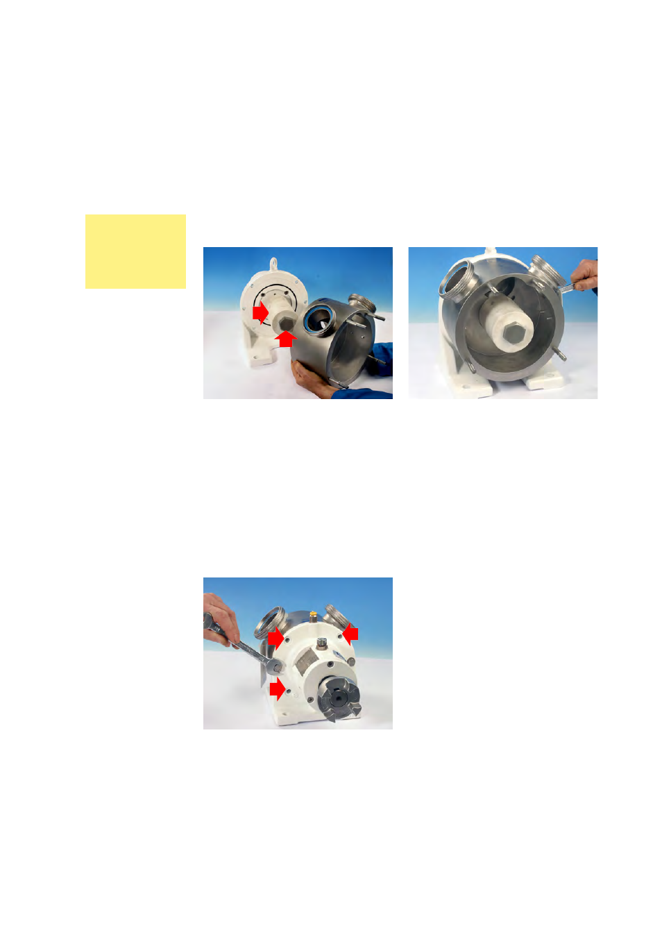
Pumps with a single mechanical seal: fitting the pump housing
l Check that the seal housing O-ring is properly positioned in its groove in the
pump housing (arrowed in bottom left picture, previous page).
l Guide the optional special cylindrical tool (arrowed: TL-SP21-002-50, TL-SP25-
002-50, TL-SP40-002-50 or TL-SP50-002-50 - available to order) over the shaft
and push it home. Push the front support locking screw (arrowed) through the
end hole of the special tool and into the female thread on the end of the shaft:
left-hand thread. Otherwise, it is important not to damage the shaft while
removing or installing the pump housing. Tighten the locking screw by hand.
l Pass the pump housing over the shaft and the special tool and position it on
the face of the power frame.
Note: The pump housing may be positioned in three orientations. See 13
Possible pump orientations.
Note: the pump housing is heavy.
l Fit the two 17mm screws (right-hand thread) and washers which secure the
pump housing to the power frame. 10-2 assembly is shown here. Alternative
screw positions (three of four arrowed) allow the pump housing to be posi-
tioned at 9-12 or 12-3 orientations. Tighten to 40Nm. Remove the locking
screw and the special tool.
Note: The SPS 300 model is pictured in this section. The SPS 400 is similar.
Note: The pictures show a pump with a cast iron power frame. Assembly of
models with stainless steel power frame is similar. For exceptions, see page 91.
SPS 250, SPS
300, SPS
400 and SPS
500 pumps
with a single
mechanical seal