Watson-Marlow SPS User Manual
Page 93
MasoSine SPS sinusoidal pumps User Manual
93
It is important to ensure that the shaft cannot rotate while the shaft locking screw
and the shaft nut are tightened. It may be convenient to secure it using a well-
padded wrench on the shaft and the key or keyway. A blocking tool for the shaft is
optionally available for easy opening of the locking screw (SPS 250: TL-SP21-010-
31, SPS 300: TL-SP25-010-31, SPS 400: TL-SP40-010-31 and SPS 500: TL-SP50-
010-31).
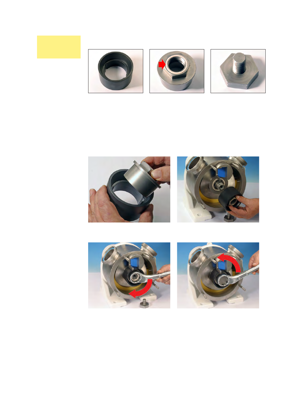
Fitting the front support, the shaft nut and locking screw
l Check that the shaft nut O-ring (arrowed) is in position on the shaft nut.
The shaft nut
The PEEK front support
The shaft locking screw
l Fit the shaft nut into the front support.
l Fit the shaft nut and front support over the shaft.
l
Use the ring spanner supplied with the pump. Tighten it (right-hand thread) to
65Nm (SPS 250); 110Nm (SPS 300); 125Nm (SPS 400); 125Nm (SPS 500).
l Fit the shaft locking screw (left-hand thread) to the shaft. Use the ring span-
ner supplied with the pump. Tighten it to 45Nm (SPS 250); 95Nm (SPS 300);
105Nm (SPS 400); 105Nm (SPS 500).
SPS 250, SPS
300, SPS 400
and SPS 500
pumps