Analog global - dual valve mode – WattMaster WCC III part 4 User Manual
Page 153
WCC III Technical Guide
3-149
WCC3.EXE SCREEN DESCRIPTIONS
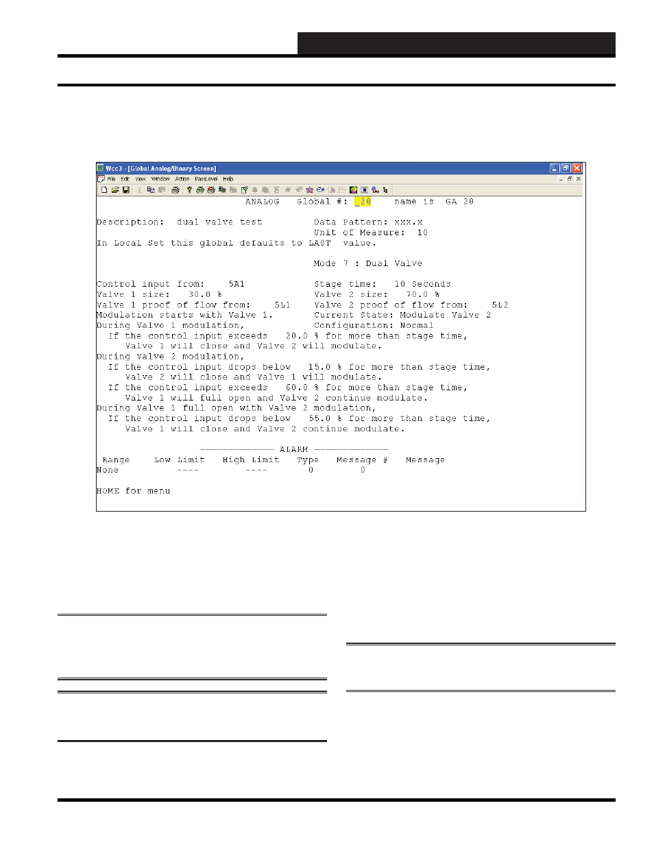
Analog Global Dual Valve Mode
Mode 7: Dual Valve
The Global Analog Mode 7 Dual Valve Screen was created to
control two valves or two VFD controlled pumps (a primary and
secondary) from one analog control point. It is not the same type of
control as Lead/Lag control.
NOTE:
The very next Global Analog is the 2nd global analog
value for Valve 2 and must be set to Global Analog Mode 6:
External for proper operation.
NOTE:
The Data Pattern for both these globals need to be set
up as XXX.X.
Control Input from:
In this fi eld, a valid WCC III analog structured value must be used
as an analog input value for this screen to operate correctly. Satellite
Analog Input (XXXAY), Satellite Data Register “a”( XXXRYa),
Satellite Data Register “b”(XXXRYb), Satellite Analog Output
(XXXPY), Global Analog (GAZZZ), where XXX equals 1 to 239,
Y equals 1 to 8, and ZZZ equals 1 to 256.
NOTE:
This input needs to be set up as a 000.0 to 100.0
(XXX.X) input, this is needed to represent 0 – 100%.
Stage time:
Stage time is the interval time for an internal stage timer counter
that is used for deciding whether to stage to/ back to / next /previous
stage. This Stage time is in Seconds.
ANALOG GLOBAL - DUAL VALVE MODE
Analog Global Screen’s WCC III Logical Address is GAXXX, where GA = Global Analog and XXX = Global Analog Address