Wcc3.exe screen descriptions, Analog input screen, Wcc iii technical guide 3-26 – WattMaster WCC III part 4 User Manual
Page 30
WCC3.EXE SCREEN DESCRIPTIONS
WCC III Technical Guide
3-26
V
OUT
GND
+V
ATI
1 TO 8
1 TO 8
NONE
LOAD
RESISTOR
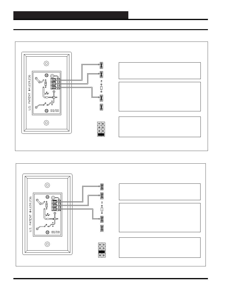
3 WIRE VOLTAGE TYPE - 0 to 1 Volt Scaling Factor
FLUSHMOUNT SENSOR (WM PART # OE222)
ANALOG INPUT SCALING - From Sat Analog Input Screen
Description:
Type: Analog General
Pattern for values associated with this input: xxx.x
Units @ 0 % Scale 0.0 DegF Units of measure message #: 1
@ full scale: 100.0 DegF Filter time constant: 8 Seconds
Input Jumper must be set to
0-1V
There are berg jumpers that are under the SAT III cover that must be set.
JOX corresponds to X = 1 to 8 for the Analog Input jumper.
Example:
JO1 is for Analog Input #1
JO8 is for Analog Input #8
An Input Load Resistor must not be used to convert the Voltage so that the
SAT III controller can calculate the proper temperature. RX
corresponds to X = 1 to 8 for the Analog Input load resistor. Example as
follows:
R1 is for Analog Input #1 (NO RESISTOR SHOULD BE INSTALLED)
R8 is for Analog Input #8 (NO RESISTOR SHOULD BE INSTALLED)
Testing with a voltmeter:
Measure from ATI to GND. You should get a voltage measurement that
corresponds to the Temperature. 0.72 Volts DC equals 72.0 Deg F
YS
101
545
RE
V.
2
RV1
C2
S1
RV2
TB1
ATI
R3
TMP
TB1
Identify the Sensor
Circuit Board YS#
YS101545
GND
AUX
OUT
R2
R1
U1
C1
JOX
THERM
0-10V
0-5V
0-1V
CONNECTIONS ON
SAT III CONTROLLER
LM-34 Type
Temp Sensor
ORANGE
WIRE
BROWN
VIOLET
WIRE
WIRE
V
OUT
GND
+V
ATI
1 TO 8
1 TO 8
NONE
LOAD
RESISTOR
3 WIRE VOLTAGE TYPE - 0 to 5 Volt Scaling Factor
FLUSHMOUNT SENSOR (WM PART # OE222)
ANALOG INPUT SCALING - From Sat Analog Input Screen
Description:
Type: Analog General
Pattern for values associated with this input: xxx.x
Units @ 0 % Scale 0.0 Deg F Units of measure message #: 1
@ full scale: 500.0 Deg F Filter time constant: 8 Seconds
Input Jumper must be set to
0-5V
There are berg jumpers that are under the SAT III cover that must be set.
JOX corresponds to X = 1 to 8 for the Analog Input jumper.
Example:
JO1 is for Analog Input #1
JO8 is for Analog Input #8
Y
S
10
154
5
RE
V
.
2
RV
1
C2
S1
RV2
TB1
ATI
R3
TMP
TB1
Identify the Sensor
Circuit Board YS#
YS101545
GND
AUX
OUT
R2
R1
U1
C1
JOX
THERM
0-10V
0-5V
0-1V
CONNECTIONS ON
SAT III CONTROLLER
LM-34 Type
Temp Sensor
ORANGE
WIRE
BROWN
VIOLET
WIRE
WIRE
An Input Load Resistor must not be used to convert the Voltage so that the
SAT III controller can calculate the proper temperature. RX
corresponds to X = 1 to 8 for the Analog Input load resistor. Example as
follows:
R1 is for Analog Input #1 (NO RESISTOR SHOULD BE INSTALLED)
R8 is for Analog Input #8 (NO RESISTOR SHOULD BE INSTALLED)
Testing with a voltmeter:
Measure from ATI to GND. You should get a voltage measurement that
corresponds to the Temperature. 0.72 Volts DC equals 72.0 Deg F
Analog Input Screen