Wcc3.exe screen descriptions – WattMaster WCC III part 4 User Manual
Page 185
WCC III Technical Guide
3-181
WCC3.EXE SCREEN DESCRIPTIONS
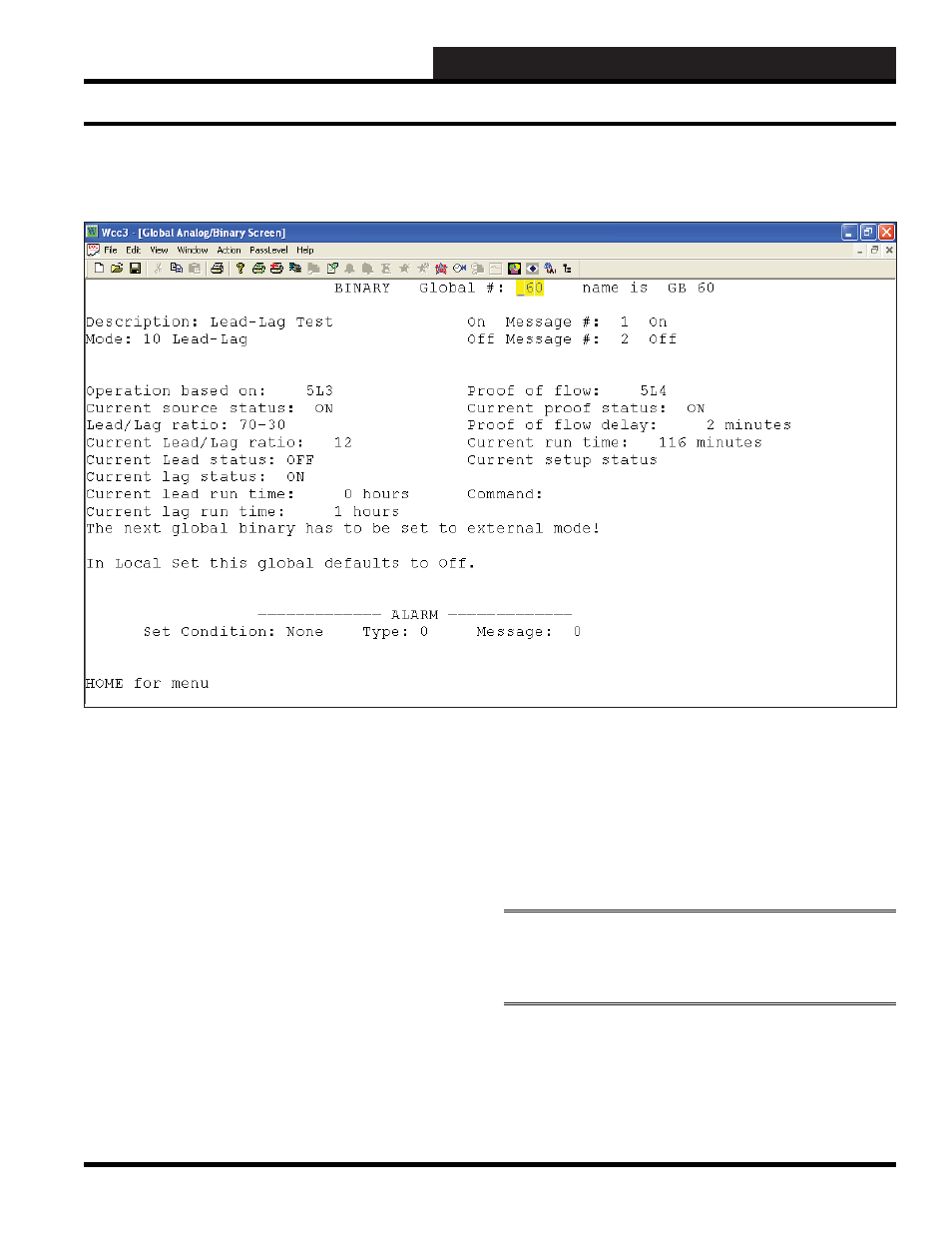
Mode: 10 Lead-Lag
Specifi es the mode used to generate the ON or OFF value of the
binary global. Because this is a choice fi eld, the following list of
available choices will be displayed at the bottom of the screen:
<Combinatorial, Compare, External, Alarm,
Alarm-by-Class, One Shot, Clock, Delay, PWM,
Lead-Lag>
Make your selection by pressing the
<space bar>
once for each
choice until the desired mode has been selected, and then press
<Enter>
. Whenever you change modes, you must fi rst clear the
existing screen by using the
<Ctrl> <Home>
feature.
Lead-Lag Mode is a dual or two-stage control scheme to balance
the operating run time between two units for redundant operation.
Each time the current source (the binary point that this global’s
operation is based on) is turned “ON”, this program will determine
which unit to turn on, either Lead or Lag, based on the current
Lead-Lag ratio and the current Lead-Lag run times.
Operation based on:
This fi eld must have a valid WCC III binary structured value that
must be used as a binary input value for this screen to operate
correctly. Satellite Binary Input (XXXLWW), Satellite Control
“C” output (XXXkYc), Satellite Control “H” output (XXXkYh)),
Satellite Binary Output (XXXOWW), Global Binary (GBZZZ),
where WW equals 1 to 16, XXX equals 1 to 239, Y equals 1 to 8,
and ZZZ equals 1 to 512.
NOTE:
The very next Global Binary is the 2nd global binary
value for the lag (Secondary) and must be set to Global Binary
“Mode 3: External” for proper operation.
Proof of fl ow:
This fi eld must have a valid WCC III binary input value and is
used as a feedback mechanism to ensure that the valve/pump has
actually turned on and is working properly.
Binary Global Lead Lag Mode Screen
BINARY GLOBAL SCREEN
LEAD LAG MODE
Binary Global Screen’s WCC III Logical Address is GBXXX, where GB = Global Binary and XXX = Global Binary Address