Wavetronix Click 111 (16-channel Contact Closure Eurocard) (CLK-111) - User Guide User Manual
Page 22
CliCk 111 • User GUIde
21
the push-button when the yellow LED in the comes on.
Note
This parameter can also be changed using the DIP switches or Click Supervisor.
This group of DIP switches determines whether the data buses are enabled to receive con-
tact closure data. Each bus can be independently enabled or disabled.
This parameter may be useful if you know a bus will not be receiving any data—for instance, if
you’re only using one sensor with your Click 111. If a bus is disabled from receiving data, then
its associated channels will not go into a fault state, even if that bus is not receiving any data.
Note
If you’ve disabled a bus from receiving data, you can still use it to configure the card
using Click Supervisor.
A disabled output will never enter the detection state, and will never indicate a fault condi-
tion. Any combination of outputs can be enabled. Due to limited space on the side label, not
all combinations of enabled and disabled channels are listed. A complete table is shown below.
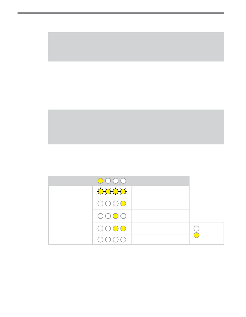
Level 1 LEDs
Bus Data Enable
Level 2 LEDs
Bus 1 & 2 Data Disabled
Bus 1 Data Enabled, Bus 2
Data Disabled
Bus 1 Data Disabled, Bus 2
Data Enabled
Bus 1 & 2 Data Enabled
(Default)
LED off
LED on
Cancel and exit menu
Table 9 – Front Panel Menu Bus Data Enable Settings
See the earlier Navigating through the Menu and the Menu Operation Example sections for
how to configure this parameter.
Because this parameter can also be set by the DIP switches, you may need to ensure that the
DIP switches are set to Software configuration mode; if they are set to Hardware, the front
panel menu will be able to display but not change these settings.