Channel allocation – Wavetronix Click 111 (16-channel Contact Closure Eurocard) (CLK-111) - User Guide User Manual
Page 26
CliCk 111 • User GUIde
25
Because this parameter can also be set by the DIP switches, you may need to ensure that the
DIP switches are set to Software configuration mode; if they are set to Hardware, the front
panel menu will be able to display but not change these settings.
Channel Allocation
The next parameter on the front panel menu label is channel allocation. To select this pa-
rameter, release the push-button when the yellow, green and blue LEDs all come on solid.
Note
This parameter can also be changed using the DIP switches or Click Supervisor.
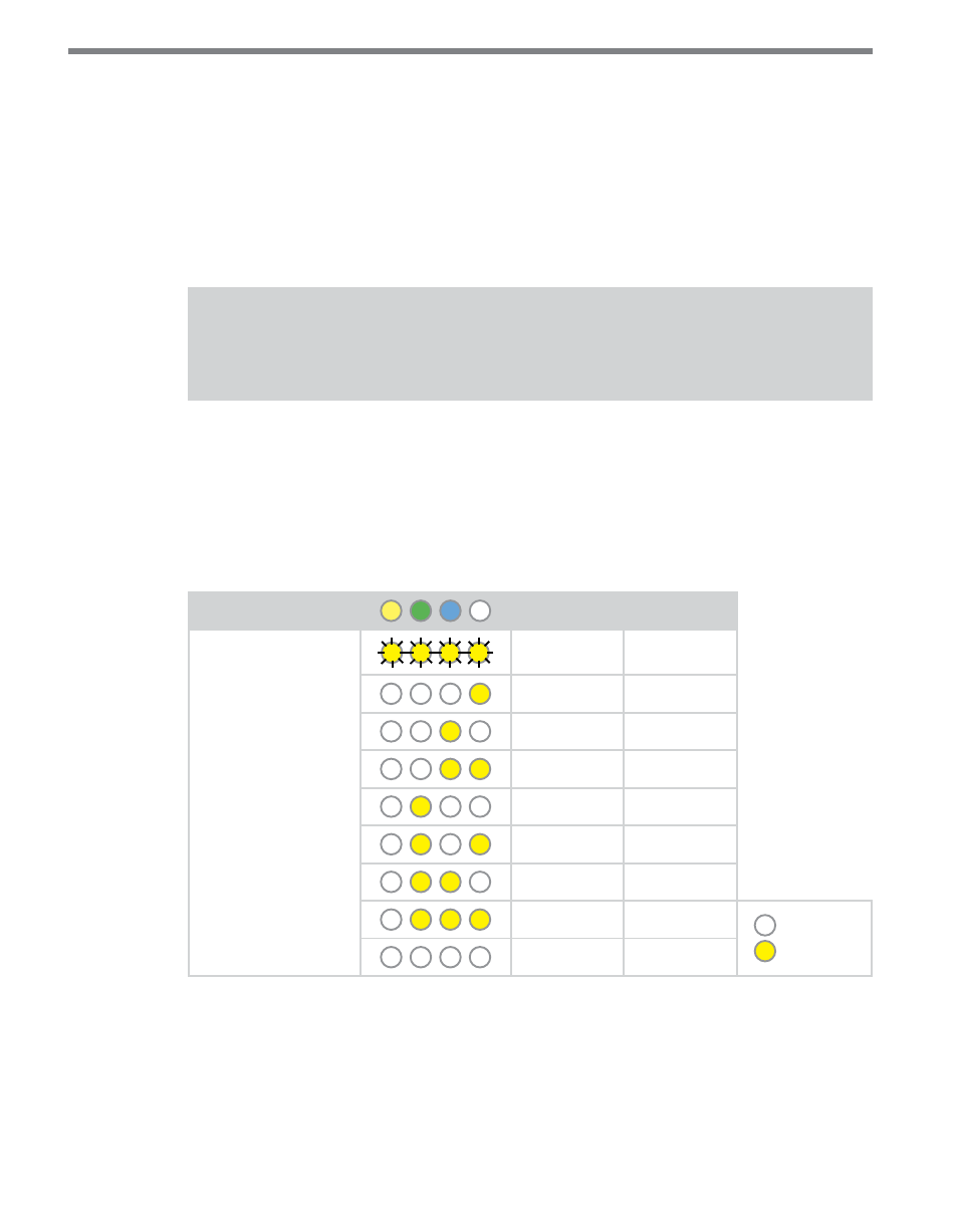
As mentioned earlier, the Click 111 device has sixteen output channels that can be distrib-
uted in various ways betweeen the two buses. This parameter allows you to choose how
many of those sixteen channels each bus should have.
The channels must be allocated in increments of two. So bus 1 could have 16 channels and
bus 2 have 0, or bus 1 have 14 and bus 2 have 2, and so on.
Level 1 LEDs
Bus 1
Bus 2
Level 2 LEDs
16 channels
0 channels
14 channels
2 channels
12 channels
4 channels
10 channels
6 channels
8 channels
8 channels
6 channels
10 channels
4 channels
12 channels
2 channels
14 channels
LED off
LED on
0 channels
16 channels
Table 13 – Front Panel Menu Channel Allocation Settings
See the earlier Navigating through the Menu and the Menu Operation Example sections for
how to configure this parameter.
Because this parameter can also be set by the DIP switches, you may need to ensure that the
DIP switches are set to Software configuration mode; if they are set to Hardware, the front