Push-button, Dip switches – Wavetronix Click 111 (16-channel Contact Closure Eurocard) (CLK-111) - User Guide User Manual
Page 6
CliCk 111 • User GUIde
5
Mode
Menu
RD TD MF PWR
1 2 3 4
Detection
1—4
5—8
9—12
13—16
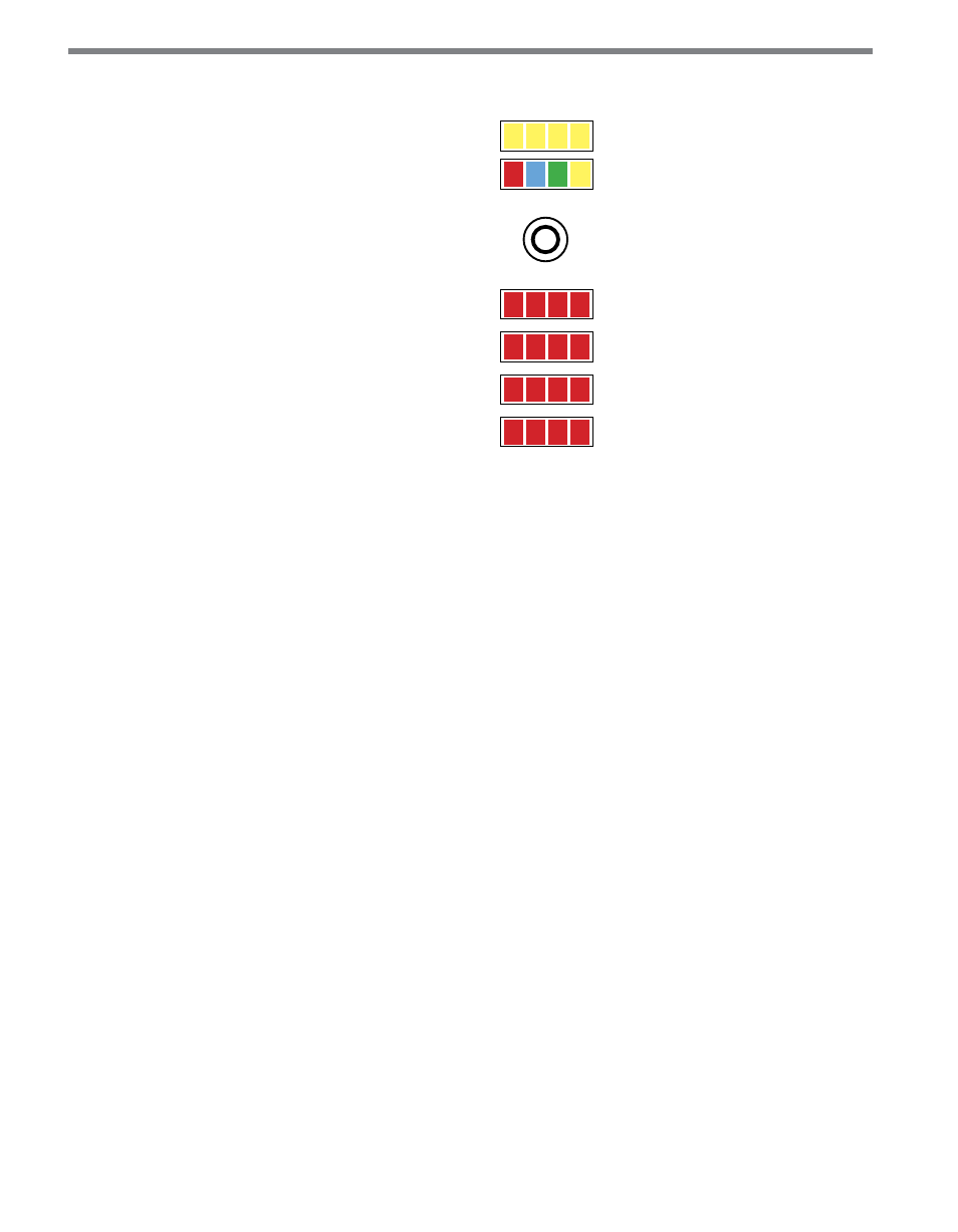
Figure 3 – Click 111 LEDs
The yellow LEDs in the top bank are used for navigating the front panel menu, which will
be discussed later, and have no other function. They are level 2 indicators and will be used
to navigate within selected menu options.
The second bank, with four different colors of LEDs, is used both for navigating the front
panel menu (they are level 1 indicators used to select menu options) and for indicating the
operating state of the device, as follows:
˽
Yellow (RD) – Lights up when the Click 111 is receiving data on any port.
˽
Green (TD) – Lights up when the device is transmitting data on any port.
˽
Blue (MF) – This LED indicates whether the device is in a fault state (MF standing for
master fault). If this LED is lit up, the device is not in a fault state. If it is extinguished,
one or both of the buses is in a fault state (the buses can enter fault states independently
of each other).
˽
Red (PWR) – Lights up when the device has power.
The lowest four banks are for detection indication. Each LED corresponds to one channel
(see the numbers next to the LEDs for the number assignations), and when a call is placed
on that channel, the LED lights up until the call ends.
Push-button
The faceplate of the Click 111 features a push-button labeled Mode. It’s used to cycle through
and select menu and configuration options.
DIP Switches
Just behind the faceplate of the Click 111, on the circuit board, is a set of DIP switches.