Physical features, Communication ports, Leds – Wavetronix Click 111 (16-channel Contact Closure Eurocard) (CLK-111) - User Guide User Manual
Page 5: 4click 111 • user guide, Figure 2 – diagram of the click 111, Dip switches
4
CliCk 111 • User GUIde
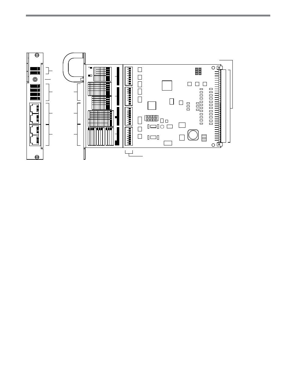
Physical Features
The following sections describe the physical features of the Click 111 card.
Mode
Switch
Menu
LEDs
RS-485
Connectors
Bus 2
RS-485
Connectors
Bus 1
Detection
LEDs
Rack Connector
DIP Switches
On
O
ff
On
O
ff
On
O
ff
On
O
ff
16 Contact
Closures
Click 111
PWR
MF
TD
RD
Detection
1 2 3 4
1–4
5–8
9–12
13–16
Menu
Mode
Da
ta: RS
-485 Bus 1
Con
tr
ol: RS
-485 Bus 2
1
2
3
4
5
6
7
8
Swit
ch 1: Baud R
ates
Bus 1
Bus 2
1
2
3
4
5
6
7
8
Bus 1
Bus 2
Swit
ch 2: Base Channel
1
2
3
4
5
6
7
8
Swit
ch 3
1
2
3
4
5
6
7
8
Swit
ch 4
On (1)
O
ff (0)
5
6
7
8
1
2
3
4
Bus 1
Bus 2
0
0
0
0
SW
0
0
0
1
960
0
0
0
1
0
1920
0
0
0
1
1
3840
0
0
1
0
0
5760
0
A
ll others
9600
5
6
7
8
1
2
3
4
0
0
0
0
SW
0
0
0
1
1
0
0
1
0
3
0
0
1
1
5
0
1
0
0
7
0
1
0
1
9
0
1
1
0
11
0
1
1
1
13
1
0
0
0
15
5
6
7
8
1
2
3
4
1
0
0
1
17
1
0
1
0
19
1
0
1
1
21
1
1
0
0
23
1
1
0
1
25
1
1
1
0
27
1
1
1
1
29
1
2
Bus
1
Bus 2
3
4
S3: C
hannel A
llo
ca
tion
S2: B
ase C
hannel
S2: B
ase C
hannel
S1: B
aud R
at
es
0
0
0
0
SW
0
0
0
1
16
0
0
1
0
14
0
0
1
1
12
0
1
0
0
10
0
1
0
1
8
0
1
1
0
6
0
1
1
1
4
1
0
0
0
2
0
2
4
6
7
8
S3: Da
ta Enable
Config: 0=SW
, 1=HW
Bus 1: 0=Enable
, 1=Dis
.
Bus 2: 0=Enable
, 1=Dis
.
1
2
3
S4: P
olarit
y
Config: 0=SW
, 1=HW
Ch: 0=L
ow
, 1=H
igh
Fault: 0=L
ow
, 1=H
igh
4
5
6
S4: F
ault
Config: 0=SW
, 1=HW
0=Enable
, 1=Disable
Sta
te: 0=C
all
, 1=No C
all
6
8
10
12
14
1
0
0
1
0
16
A
ll others
8
8
Ch. A
lloc
.
Da
ta En.
Polar
ity
Fault
Bus 1
Bus 2
Bus 1
Bus 2
Figure 2 – Diagram of the Click 111
Communication Ports
The Click 111 contains two independent serial communications ports, each of which can be
connected to a sensor (so two sensors can talk to each card). Each port is made up of two
RJ-11 connectors, which make it simple to daisy-chain multiple Click 111 cards together
and create a RS-485 bus. The two RJ-11 RS-485 data buses can be connected to a SmartSen-
sor through a Click surge protection module, or through a serial data converter.
The buses are labeled as Bus 1 and Bus 2, though as both buses are identical it does not mat-
ter which is used for which sensor. Be aware that this means there is no dedicated port for
configuration, meaning that in order to configure the device, you must change the wiring
of your cabinet or use a single bus for both data and configuration; in this case, data report-
ing will be temporarily halted during configuration. Be aware that if data isn’t received on a
Click 111 bus for ten seconds, that bus will go into a fault state.
LEDs
The faceplate of the Click 111 has six banks of LEDs.