Wavetronix Click 111 (16-channel Contact Closure Eurocard) (CLK-111) - User Guide User Manual
Page 33
32
CliCk 111 • User GUIde
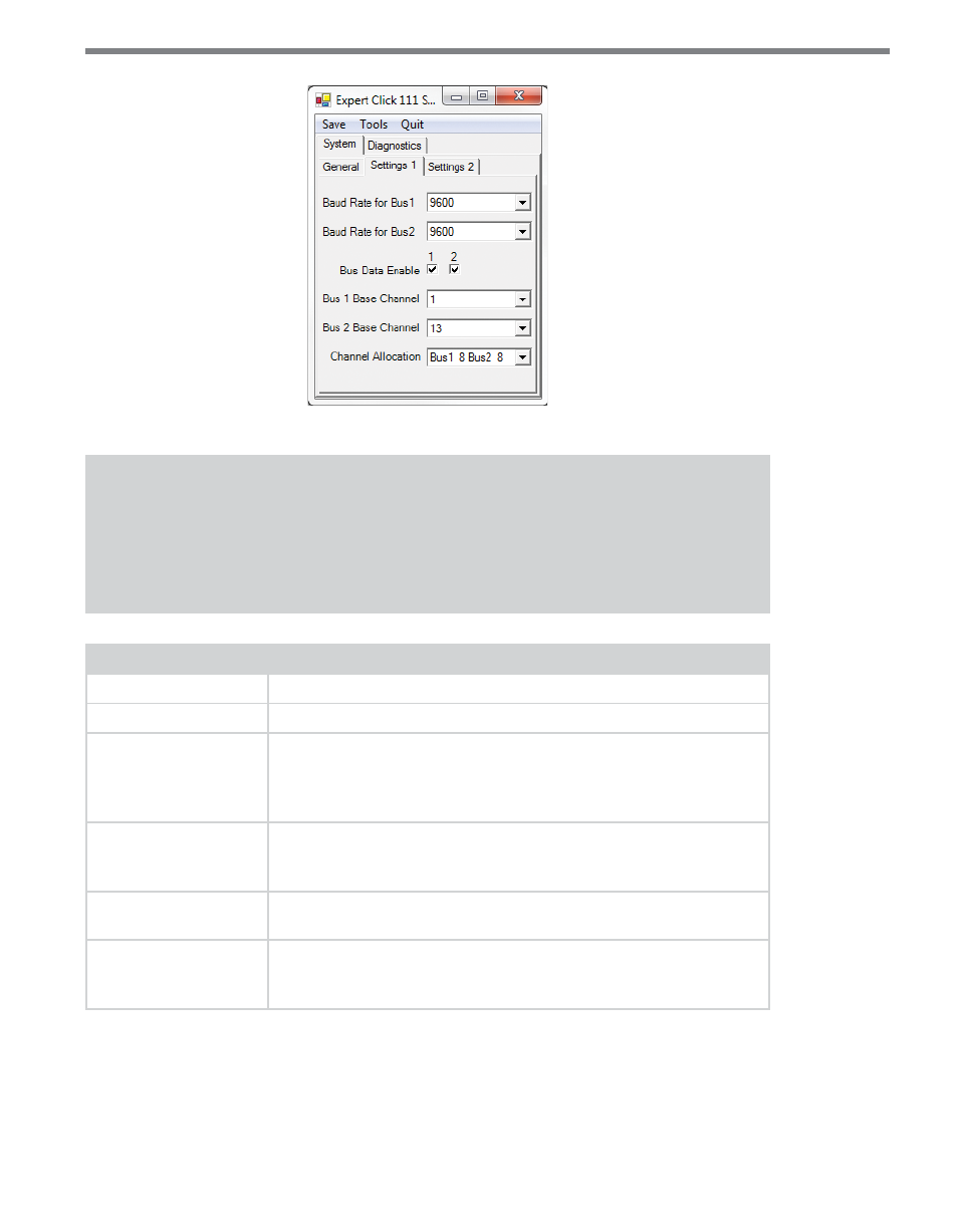
Figure 10 – Expert Driver Settings 1 Tab
Note
These parameters can also be configured using the DIP switches or the front panel
menu; if in the DIP switches they are set to Hardware mode, the parameters will ap-
pear grayed out on this screen.
Setting
Description
Baud Rate for Bus 1
Lets you change the baud rate, in bps, of bus 1.
Baud Rate for Bus 2
Lets you change the baud rate, in bps, of bus 2.
Bus Data Enable
Lets you enable or disable the data on both buses. If you disable a
bus, it will ignore whether or not it’s receiving data. This can be useful
if you know a bus won’t be receiving any data; disabling it will ensure
that it doesn’t go into a fault state.
Bus 1 Base Channel
Lets you select the starting sensor channel that will be mapped to
bus 1 output channel 1. For example, if this is set to 7, then sensor
channel 7 will be mapped to bus 1 output channel 1.
Bus 2 Base Channel
Lets you select the starting sensor channel that will be mapped to
bus 2 output channel 1.
Channel Allocation
Lets you choose how many of the card’s 16 channels will be allocated
to each bus. This must be done in increments of two: bus 1 = 16 chan-
nels and bus 2 = 0, or bus 1 = 14 channels and bus 2 = 2, and so on.
Table 20 – Expert Driver Settings Tab
The System > Settings 2 tab has the following parameters (see Figure 11 and Table 21):