Installation – Westermo ID-90 User Manual
Page 6
6
1
2
3
4
5
6
7
8
9
110-240 VDC
95-240 VAC
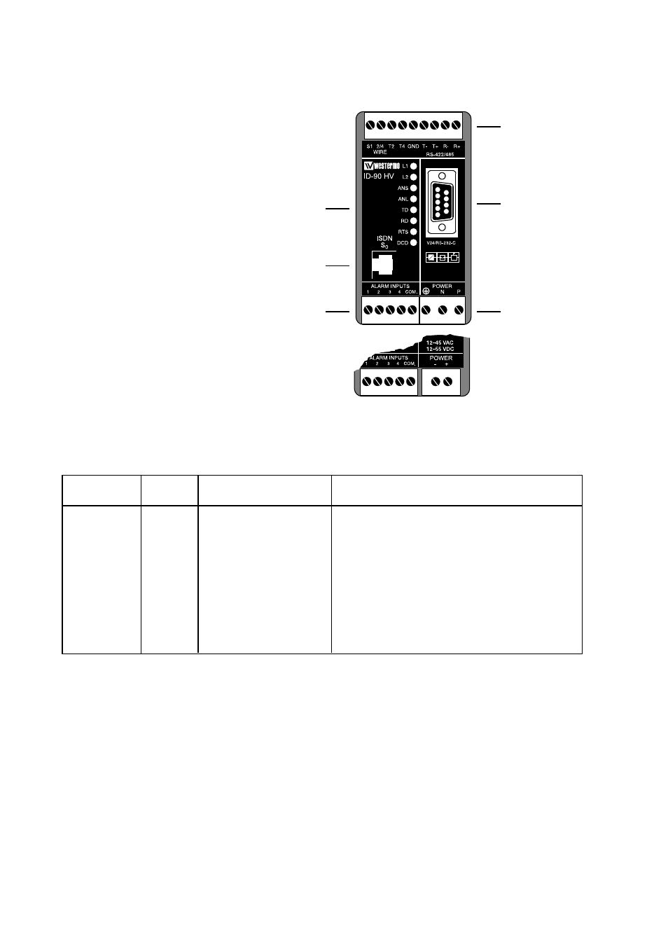
Installation
The Terminal Adapter should be connected in the following way:
Power connection is made through screw-block
at bottom right corner.
For HV-version a 3-pole connector,
and for LV-version a 2-pole connector is used.
Computers or other equipment
are connected through an
RS-232/V.24 or RS-485 connec-
tion. The RS-232/V.24 uses a
9-pole D-sub and the RS-485
a 9-pole screw connector.
Do not use ribbon cable
for RS-232/V.24 connections.
Light emit-
ting diodes
Screw-block
for RS-422/485
connection
9-pole D-sub
for RS-232/V.24
connection
Power
connection
Line connec-
tion RJ-45
Alarm
connection
▼
▼
▼
▼
▼
▼
RS-232/V.24 Connections
Pinouts for the 9-pole D-sub
O
11
09
DCD/Data Carrier Detect
O
2
104
RD/Received Data
I
3
103
TD/Transmitted Data
I
4
108/2
DTR/Data Terminal Ready
–
5
102
SG/Signal Ground
O
6
107
DSR/Data Set Ready
I
7
105
RTS/Request to Send
O
8
106
CTS/Clear to Send
O
9
125
RI/Ring Indicator
Signal description
I = input O = output on ID-90
Direction
Pin
no.
CCITT V.24
Description
6607-2204
ID-90 LV