Isdn – Westermo ID-90 User Manual
Page 90
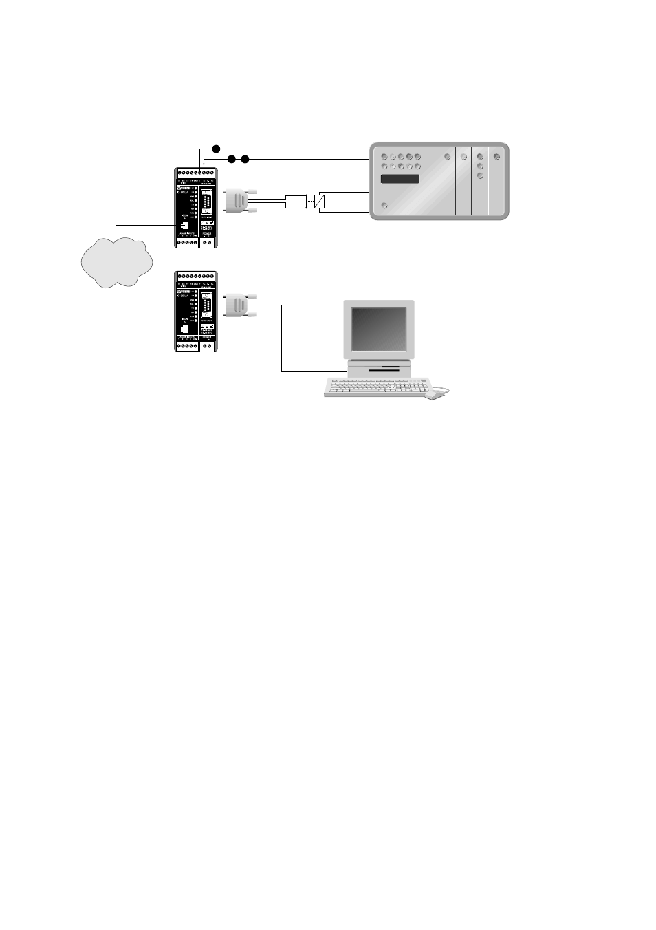
Dial up with hardware signalling.
Dial-up can be made by sending an arbitrary character to ID-90 and the DTR-pin can be
used to disconnect. A typical application using this method is shown in the example
below. The PLC periodically polls a supervisory system, the poll causes the ID-90 to
establish a connection to the supervisory system. The PLC also controls the connection
breakdown through the contact connecting DSR and DTR. The contact shall normally be
closed and only opened shortly to break down the connection.
The number(s) to be called is controlled by the variables catab1 – catab3
The modem does not have a redialling function. If necessary this must be handled by
other equipment connected. The RS-232/V.24 control signal DCD can be used to indicate
the success of connection.
Before the command mode is set to Tx hotline the numbers to be dialled has to be defined
by the below command.
AT**catabX=nn
Where X is 1,2 or 3 and nn the number to dial.
The ID-90 will first try to dial the number stored for
catab1 and continue to establish connection to the
number stored for catab2 if connection to catab1 is
unsuccessful. Only catab1 has to be defined if only
one number is to be called.
AT**save
Save the number(s).
Now power down the ID 90 and set the DIP-switches according to below figure.
After switches has been set power up the ID 90 again (the switches is only reed
by ID-90 at power on)
90
6607-2204
1
2
3
4
5
6
7
8
9
1
2
3
4
5
6
7
8
9
ISDN
67490 89
4 DTR
RS-485
RS-232
6 DSR
7
4
3