Description direction terminal name – Westermo ID-90 User Manual
Page 7
I
1R+ (A’)
ID-90 Receive
I
2
R– (B’)
ID-90 Receive
I/O
3
T+ (A)
ID-90 Transmit, at RS-485
I/O
4
T– (B)
ID-90 Transmit, at RS-485 Bidirectional
–
5
Shield
If shielded cable is used, connect the shield
only at one end to avoid ground currents.
–
6
T4
Termination 4-wire, connect to terminal 2
to terminate a 4-wire connection.
–
7
T2
Termination 2-wire, connect to terminal 3
to terminate a 2-wire connection.
–
8
2-/4-wire
2/4 wire input selector. Input open selects
2-wire and connected to terminal 9 for 4-wire.
–
9
S1Select 1
.Wired to terminal 8 when 4-wire con-
nection is used. Internally connected to +5V
via pull-up resistor.
7
6607-2204
I = input O = output on ID-90
The definations R+/R–,T+/T– can be various between different manufactures.
ID-90 uses the defination that in a “MARK”-condition R+/T+ is more negative than R–/T–.
Description
Direction
Terminal
Name
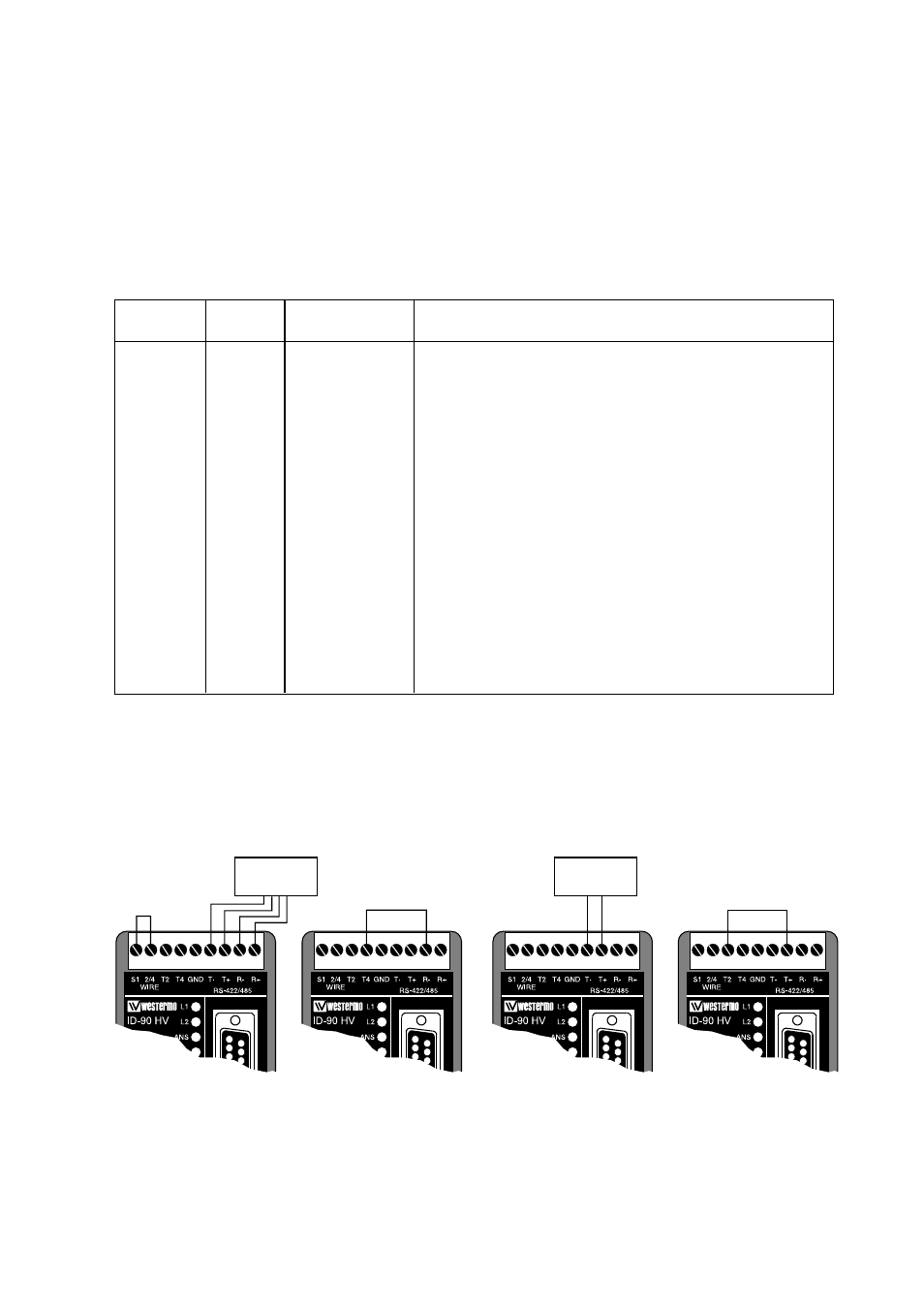
RS-422/485 interface connection
The ID-90 is supplied with a RS-422/485 interface.
The RS-422/485 interface is internally in parallel to the RS-232/V.24 interface using the
9-pole D-sub. The two interfaces can not be used or be connected simultaneously, but the
interface connected will automatically be selected as the DTE source.
The RS-422/485 connections are made as shown below. Please note that the selection
of 2- or 4- wire and termination or no termination is done by linking between some of the
screw terminals.
Termination
4-wire
Termination
2-wire
4-wire
Connection
of RS-422
Connection
of RS-485
1
2
3
4
5
6
7
8
9
1
2
3
4
5
6
7
8
9
1
2
3
4
5
6
7
8
9
1
2
3
4
5
6
7
8
9